A wiring diagram for a GM High Energy Ignition (HEI) Distributor illustrates the electrical connections between the HEI distributor, ignition coil, and other components in a vehicle’s ignition system. It provides a roadmap for troubleshooting and servicing the ignition system, ensuring proper functionality for reliable engine operation.
The wiring diagram outlines the proper connections for the HEI module, ignition coil, battery, starter, and tachometer, enabling technicians to accurately diagnose issues related to starting, ignition timing, and misfires. Its importance lies in providing a comprehensive guide for maintaining the integrity of the ignition system, ensuring optimal engine performance and fuel efficiency.
The transition to electronic ignition systems in the automotive industry marked a significant advancement in ignition technology. The HEI distributor played a pivotal role in this development, offering improved spark consistency, higher voltage output, and reduced maintenance compared to conventional ignition systems.
Understanding the essential aspects of “Wiring Diagram for GM HEI Distributor” is crucial for comprehending the intricacies of this automotive component. These aspects encompass the fundamental characteristics, functions, and significance of the wiring diagram in the context of the HEI distributor.
- Electrical Connections: The wiring diagram outlines the electrical pathways between the HEI distributor, ignition coil, battery, and other ignition system components.
- Troubleshooting Guide: It serves as a valuable tool for diagnosing and resolving issues related to starting, ignition timing, and misfires.
- Ignition System Maintenance: The diagram provides guidance for maintaining the integrity and functionality of the ignition system, ensuring optimal engine performance.
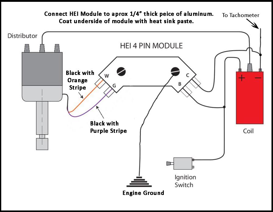
- HEI Module Connections: It specifies the proper connections for the HEI module, which controls the ignition timing and spark distribution.
- Ignition Coil Connections: The diagram indicates the connections between the HEI distributor and the ignition coil, which generates the high voltage required for spark ignition.
- Battery and Starter Connections: It outlines the electrical connections to the battery and starter, which supply power to the ignition system.
- Tachometer Connections: The diagram may also include instructions for connecting a tachometer, which measures engine speed.
- Compatibility: The wiring diagram is specific to GM HEI distributors, ensuring compatibility and accurate installation.
These essential aspects collectively contribute to the effective utilization of the wiring diagram for GM HEI distributors. It serves as a comprehensive guide for technicians and DIY enthusiasts alike, enabling them to maintain, troubleshoot, and optimize the ignition system for reliable engine operation.
Electrical Connections
The electrical connections outlined in the wiring diagram play a critical role in the proper functioning of the GM HEI distributor. Without a clear understanding of these connections, troubleshooting and servicing the ignition system can be challenging. The diagram serves as a comprehensive guide, enabling technicians to accurately diagnose and resolve issues related to starting, ignition timing, and misfires.
For instance, the wiring diagram specifies the proper connections between the HEI module and the ignition coil. The HEI module controls the ignition timing and spark distribution, while the ignition coil generates the high voltage required for spark ignition. Incorrect connections between these components can lead to engine performance issues, such as misfiring and difficulty starting.
Furthermore, the wiring diagram outlines the electrical pathways between the HEI distributor and the battery and starter. These connections ensure that the ignition system receives the necessary power to operate effectively. Understanding these connections is essential for diagnosing and resolving electrical problems within the ignition system.
In summary, the electrical connections outlined in the wiring diagram for the GM HEI distributor are critical for maintaining the integrity and functionality of the ignition system. By providing a clear roadmap for troubleshooting and servicing, the diagram empowers technicians to optimize engine performance and ensure reliable operation.
Troubleshooting Guide
The troubleshooting guide is an indispensable component of the wiring diagram for the GM HEI distributor. It provides a step-by-step approach to diagnosing and resolving common ignition system issues, such as starting problems, ignition timing malfunctions, and misfires. By following the troubleshooting guide, technicians can systematically identify and address the root cause of these issues, ensuring optimal engine performance and reliability.
For instance, if an engine is experiencing difficulty starting, the troubleshooting guide can help technicians determine whether the issue lies within the ignition system or elsewhere in the vehicle. By testing the ignition coil, HEI module, and other components, technicians can isolate the source of the problem and implement the appropriate repair or replacement.
Furthermore, the troubleshooting guide provides valuable insights into ignition timing and misfire issues. It outlines the proper ignition timing settings for different engine configurations and explains how to adjust the timing if necessary. Additionally, the guide offers diagnostic techniques for identifying and resolving misfires, which can be caused by a variety of factors, such as faulty spark plugs, ignition wires, or fuel injector issues.
In summary, the troubleshooting guide is a critical component of the wiring diagram for the GM HEI distributor. It empowers technicians with the knowledge and guidance to diagnose and resolve ignition system issues accurately and efficiently, ensuring optimal engine performance and reliability.
Ignition System Maintenance
Within the context of the “Wiring Diagram for GM HEI Distributor,” ignition system maintenance plays a crucial role in ensuring the reliable operation and optimal performance of an engine. The diagram provides valuable guidance for technicians and enthusiasts alike, enabling them to maintain the integrity and functionality of the ignition system through various maintenance procedures and checks.
- Component Inspection and Replacement: The wiring diagram facilitates the identification and inspection of critical ignition system components, such as spark plugs, ignition wires, and the distributor cap and rotor. Regular inspection and timely replacement of worn or damaged components help prevent ignition system failures and ensure optimal spark delivery.
- Ignition Timing Adjustment: The diagram provides insights into the proper ignition timing settings for different engine configurations. Accurate ignition timing is essential for maximizing engine power and efficiency, and the diagram guides technicians in making necessary adjustments based on the vehicle’s specifications.
- Electrical Connections: Maintaining proper electrical connections is crucial for the reliable operation of the ignition system. The wiring diagram outlines the correct connections between the HEI distributor, ignition coil, battery, and other components. Regular inspection and cleaning of electrical terminals and connectors prevent corrosion and ensure optimal current flow.
- Troubleshooting and Diagnostics: The wiring diagram serves as a valuable tool for troubleshooting and diagnosing ignition system issues. By following the diagram, technicians can systematically identify and resolve problems related to starting, misfires, and ignition timing malfunctions, ensuring the efficient operation of the engine.
In conclusion, the “Wiring Diagram for GM HEI Distributor” encompasses vital information for maintaining the integrity and functionality of the ignition system. By providing guidance on component inspection, ignition timing adjustment, electrical connections, and troubleshooting, the diagram empowers technicians and enthusiasts to optimize engine performance, ensure reliability, and address ignition system issues effectively.
HEI Module Connections
Within the context of the “Wiring Diagram for GM HEI Distributor,” the HEI module plays a central role in controlling the ignition timing and spark distribution, which are critical factors in ensuring efficient engine operation. The wiring diagram outlines the proper electrical connections for the HEI module, providing a roadmap for technicians and enthusiasts to maintain and troubleshoot the ignition system effectively.
The HEI module receives input signals from various engine sensors, such as the crankshaft position sensor and the camshaft position sensor. Based on these inputs, the HEI module calculates the optimal ignition timing and controls the spark distribution to the engine’s spark plugs. Proper connections are essential for the HEI module to function correctly and deliver the necessary spark energy at the right time during the engine cycle.
For instance, if the HEI module is not correctly connected to the ignition coil, the spark plugs may not receive sufficient voltage to generate a strong spark. This can lead to misfires, reduced engine power, and increased fuel consumption. The wiring diagram provides clear instructions on connecting the HEI module to the ignition coil, ensuring proper spark delivery and optimal engine performance.
Furthermore, the wiring diagram outlines the connections between the HEI module and other components, such as the battery, starter, and tachometer. These connections are crucial for providing power to the HEI module and enabling it to communicate with other engine management systems. By understanding these connections, technicians can diagnose and resolve issues related to starting, ignition timing, and engine performance.
In summary, the proper connections for the HEI module, as specified in the wiring diagram for GM HEI distributors, are essential for maintaining optimal ignition system functionality. By providing a clear understanding of these connections, the wiring diagram empowers technicians and enthusiasts to ensure reliable engine operation, diagnose ignition system issues, and optimize engine performance.
Ignition Coil Connections
Within the context of the “Wiring Diagram for GM HEI Distributor,” the ignition coil connections play a crucial role in the generation and delivery of high voltage required for spark ignition in internal combustion engines. The wiring diagram provides a detailed layout of these connections, enabling technicians and enthusiasts to understand, troubleshoot, and maintain the ignition system effectively.
The ignition coil is a critical component of the ignition system, responsible for converting the relatively low voltage from the battery into the high voltage necessary to create a spark across the spark plugs. The wiring diagram outlines the electrical connections between the HEI distributor and the ignition coil, ensuring the proper flow of current and the generation of sufficient voltage for ignition.
For instance, if the ignition coil is not correctly connected to the HEI distributor, the spark plugs may not receive the necessary high voltage, leading to misfires, reduced engine power, and increased fuel consumption. The wiring diagram provides clear instructions on connecting the ignition coil to the HEI distributor, ensuring optimal spark generation and engine performance.
Furthermore, the wiring diagram also indicates the connections between the ignition coil and other components, such as the battery, starter, and ignition switch. Understanding these connections is essential for diagnosing and resolving issues related to starting, ignition timing, and engine performance. By tracing the ignition coil connections outlined in the wiring diagram, technicians can identify and fix problems in the ignition system, ensuring reliable engine operation.
In summary, the ignition coil connections, as detailed in the “Wiring Diagram for GM HEI Distributor,” are critical for maintaining a functional ignition system. The wiring diagram empowers technicians and enthusiasts to understand, troubleshoot, and maintain the ignition system effectively, ensuring optimal engine performance and reliable operation.
Battery and Starter Connections
Within the context of the “Wiring Diagram for GM HEI Distributor,” the battery and starter connections play a fundamental role in providing the electrical power necessary for the ignition system to function. The wiring diagram outlines these connections, enabling technicians and enthusiasts to understand, diagnose, and maintain the ignition system effectively.
The battery is the primary source of electrical power for the ignition system. It provides the voltage necessary to generate the spark at the spark plugs, which ignites the air-fuel mixture in the engine’s cylinders. The starter draws power from the battery to crank the engine, initiating the combustion process. Without proper connections to the battery and starter, the ignition system cannot generate the necessary spark to start the engine or maintain its operation.
For instance, if the battery terminals are loose or corroded, the electrical current may not flow properly to the ignition system, leading to starting problems or intermittent ignition failures. The wiring diagram provides clear instructions on connecting the battery to the ignition system, ensuring optimal power supply and reliable engine operation.
Furthermore, the wiring diagram outlines the connections between the starter and the ignition system. The starter solenoid engages the starter motor, which cranks the engine and generates the initial spark necessary for ignition. Understanding these connections is essential for diagnosing and resolving starting issues, such as a faulty starter solenoid or a broken connection between the starter and the ignition switch.
In summary, the battery and starter connections, as detailed in the “Wiring Diagram for GM HEI Distributor,” are critical for maintaining a functional ignition system. The wiring diagram empowers technicians and enthusiasts to understand, troubleshoot, and maintain the ignition system effectively, ensuring reliable engine starting and operation.
Tachometer Connections
Tachometer connections are an integral part of the “Wiring Diagram for GM HEI Distributor,” providing valuable information about engine performance. The diagram outlines the electrical connections necessary to install and operate a tachometer, enabling technicians and enthusiasts to monitor engine speed accurately.
- Compatibility with HEI Distributors: The wiring diagram ensures compatibility between the HEI distributor and the tachometer. It specifies the correct connections for different types of HEI distributors, ensuring accurate readings and reliable engine monitoring.
- Wiring Instructions: The diagram provides detailed wiring instructions for connecting the tachometer to the HEI distributor. It includes information on wire colors, terminal locations, and grounding points, enabling proper installation and signal transmission.
- Signal Processing: The diagram explains how the tachometer processes the signal from the HEI distributor. It describes the conversion of the distributor’s pulses into a readable RPM value, allowing the tachometer to display accurate engine speed information.
- Troubleshooting Guide: The wiring diagram often includes a troubleshooting guide for tachometer connections. It assists in diagnosing and resolving common issues, such as incorrect readings, intermittent signals, or tachometer failure.
In summary, the tachometer connections outlined in the “Wiring Diagram for GM HEI Distributor” are essential for monitoring engine speed accurately. The diagram provides comprehensive instructions, ensures compatibility, explains signal processing, and offers troubleshooting guidance, empowering technicians and enthusiasts to maintain optimal engine performance and ensure reliable operation.
Compatibility
Within the context of “Wiring Diagram for GM HEI Distributor,” compatibility plays a crucial role in ensuring the proper functionality and accurate installation of the ignition system. The wiring diagram is specifically designed for GM HEI distributors, taking into account their unique electrical characteristics and connection requirements. This compatibility aspect encompasses several key facets:
- Dedicated Connections: The wiring diagram provides precise instructions for connecting the HEI distributor to other components, such as the ignition coil, battery, starter, and tachometer. These dedicated connections ensure that the electrical signals are transmitted correctly, preventing compatibility issues that could lead to misfires, ignition timing problems, or incorrect readings.
- Electrical Specifications: The wiring diagram considers the electrical specifications of GM HEI distributors, including voltage requirements, current draw, and signal timing. By matching the wiring to the distributor’s electrical needs, the diagram ensures optimal performance and longevity of the ignition system.
- Physical Compatibility: The physical dimensions and mounting points of GM HEI distributors are taken into account in the wiring diagram. This ensures that the distributor can be installed securely and aligned correctly with other engine components, preventing any mechanical interference or electrical shorts.
- Troubleshooting and Maintenance: The compatibility of the wiring diagram with GM HEI distributors simplifies troubleshooting and maintenance procedures. By following the diagram’s instructions, technicians can easily identify and resolve any electrical issues or perform routine maintenance tasks, ensuring reliable operation of the ignition system.
In summary, the compatibility of the wiring diagram with GM HEI distributors is paramount for achieving accurate installation, optimal performance, and efficient troubleshooting. The specific design considerations and dedicated connections ensure that the ignition system functions as intended, maximizing engine performance and reliability.


Related Posts


