Wiring Diagram for Pit Bike: A comprehensive visual representation that illustrates the electrical connections and components within a pit bike, enabling proper installation, maintenance, and troubleshooting.
Importance, Benefits, and Historical Context: Wiring diagrams are essential for ensuring the safe and efficient operation of pit bikes, as they provide technicians and riders with an accurate map of the electrical system. The historical development of these diagrams has aligned with advancements in pit bike designs, ensuring optimal performance.
This article will delve into the specifics of wiring diagrams for pit bikes, examining their components, usage, and significance in maintaining optimal electrical functionality.
Wiring diagrams are crucial for understanding the electrical systems of pit bikes, providing a visual representation of the connections between components. Key aspects of wiring diagrams for pit bikes include:
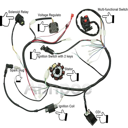
- Components: Diagrams identify and locate electrical components such as batteries, ignition coils, and switches.
- Connections: They illustrate the pathways of electrical current flow, indicating wire colors and terminal locations.
- Troubleshooting: Diagrams aid in diagnosing electrical issues by providing a reference for tracing circuits and identifying potential faults.
- Modifications: When customizing or repairing pit bikes, diagrams guide the addition or removal of electrical components.
- Safety: By ensuring proper connections, diagrams prevent electrical hazards and maintain the safe operation of pit bikes.
- Standardization: Diagrams adhere to industry standards, facilitating communication among technicians and riders.
- Efficiency: Diagrams streamline the installation and maintenance of electrical systems, saving time and effort.
- Performance: Accurate wiring diagrams optimize electrical performance, ensuring the reliable operation of pit bikes.
These aspects collectively contribute to the effective design, maintenance, and troubleshooting of pit bike electrical systems, enhancing their overall performance and safety.
Components
Within the context of “Wiring Diagram For Pit Bike”, understanding the components of an electrical system is paramount. Wiring diagrams provide a visual representation of these components and their connections, aiding in the installation, maintenance, and troubleshooting of pit bike electrical systems.
- Identification of Components: Diagrams clearly label and depict electrical components such as batteries, ignition coils, switches, and other essential components, ensuring a clear understanding of their location and function.
- Circuit Tracing: By illustrating the flow of electrical current, diagrams allow technicians and riders to trace circuits, identify connections, and pinpoint potential issues within the electrical system.
- Component Specifications: Diagrams often include specifications and details about electrical components, such as their voltage, amperage, and wattage ratings, which are crucial for proper installation and maintenance.
- Standardized Symbols: Wiring diagrams adhere to industry-standard symbols, ensuring universal understanding and facilitating communication among technicians and riders, regardless of their background or experience level.
Overall, the identification and location of electrical components through wiring diagrams are fundamental aspects of “Wiring Diagram For Pit Bike”, providing a comprehensive understanding of the electrical system and enabling effective maintenance, troubleshooting, and customization of pit bikes.
Connections
In the context of “Wiring Diagram For Pit Bike”, connections play a pivotal role in understanding and manipulating the flow of electrical current within the pit bike’s electrical system. Wiring diagrams illustrate these connections, indicating wire colors and terminal locations, which are crucial for proper installation, maintenance, and troubleshooting.
Connections establish the pathways through which electrical current flows, allowing various components within the electrical system to communicate and function together. By indicating wire colors and terminal locations, wiring diagrams provide a clear visual guide for technicians and riders to trace circuits, identify connections, and pinpoint potential issues.
For instance, consider the ignition system of a pit bike. The wiring diagram illustrates the connections between the battery, ignition coil, spark plug, and other components. By following the wire colors and terminal locations, a technician can verify the proper flow of current, ensuring that the engine receives the necessary spark to start and run.
Furthermore, when customizing or repairing pit bikes, understanding connections is essential. Wiring diagrams guide the addition or removal of electrical components, ensuring that connections are made correctly and in accordance with the bike’s electrical system. This understanding empowers riders and technicians to personalize their pit bikes while maintaining optimal performance and safety.
In summary, connections, as illustrated by wire colors and terminal locations in wiring diagrams, are a critical aspect of “Wiring Diagram For Pit Bike”. They provide a roadmap for electrical current flow, enabling effective installation, maintenance, troubleshooting, and customization of pit bikes.
Troubleshooting
In the context of “Wiring Diagram For Pit Bike”, troubleshooting is a crucial aspect of maintaining optimal electrical performance. Wiring diagrams serve as invaluable tools in diagnosing electrical issues, providing a reference for tracing circuits and identifying potential faults.
When electrical problems arise, wiring diagrams empower technicians and riders to systematically troubleshoot the system. By tracing circuits and analyzing connections, they can pinpoint the source of the issue, whether it’s a faulty component, a loose connection, or a short circuit.
For example, if a pit bike experiences intermittent electrical failures, the wiring diagram guides the technician in tracing the circuit responsible for the affected components. By following the wire colors and terminal locations, they can identify loose connections, damaged wires, or faulty components, enabling targeted repairs.
Furthermore, wiring diagrams facilitate the identification of potential faults before they manifest as major problems. By proactively inspecting connections and tracing circuits, technicians can identify areas prone to wear and tear or potential electrical hazards, allowing for timely maintenance and preventive measures.
In summary, troubleshooting is an essential component of “Wiring Diagram For Pit Bike”, providing a structured approach to diagnosing electrical issues. Wiring diagrams empower technicians and riders to trace circuits, identify potential faults, and implement effective repairs, ensuring the reliable and safe operation of pit bikes.
Modifications
In the context of “Wiring Diagram For Pit Bike”, modifications play a significant role in customizing and repairing pit bikes, and wiring diagrams serve as essential guides during these processes. When customizing pit bikes, riders often add or remove electrical components to enhance performance or aesthetics. Wiring diagrams guide these modifications by providing a clear understanding of the electrical system and its connections.
For instance, when installing an aftermarket exhaust system, the wiring diagram guides the rider in identifying the correct wires to connect to the new exhaust sensor. Similarly, when adding auxiliary lighting, the diagram ensures proper connection to the battery and switch.
In repairs, wiring diagrams are crucial for troubleshooting and replacing faulty electrical components. By tracing circuits and identifying connections, technicians can pinpoint the source of the problem and efficiently make repairs.
The understanding gained from wiring diagrams empowers riders and technicians to confidently customize and repair their pit bikes, ensuring optimal performance and safety.
In summary, modifications, whether for customization or repairs, are a critical aspect of “Wiring Diagram For Pit Bike”. Wiring diagrams provide a comprehensive guide to adding or removing electrical components, enabling riders and technicians to modify their pit bikes effectively and safely.
Safety
In the context of “Wiring Diagram For Pit Bike”, safety is paramount. Wiring diagrams play a crucial role in preventing electrical hazards and maintaining the safe operation of pit bikes by ensuring proper connections.
Electrical hazards can arise from loose connections, incorrect wiring, or damaged components. Wiring diagrams provide a clear and comprehensive guide to electrical connections, minimizing the risk of these hazards. By following the diagrams, riders and technicians can ensure that wires are correctly connected to the appropriate terminals, preventing short circuits, overheating, and potential fires.
For example, a poorly connected battery terminal can lead to arcing and sparking, posing a significant safety risk. The wiring diagram guides the proper installation of the battery, ensuring a secure connection that prevents such hazards.
Furthermore, wiring diagrams facilitate the identification and repair of faulty components. By tracing circuits and analyzing connections, technicians can pinpoint the source of electrical problems, enabling timely repairs and preventing further damage or safety risks.
In summary, safety is a fundamental aspect of “Wiring Diagram For Pit Bike”. Wiring diagrams are essential for ensuring proper connections, preventing electrical hazards, and maintaining the safe operation of pit bikes, making them a critical component for riders and technicians.
Standardization
In the context of “Wiring Diagram For Pit Bike”, standardization plays a pivotal role in facilitating communication among technicians and riders. By adhering to industry standards, wiring diagrams establish a common language, ensuring that electrical systems are designed, installed, and maintained consistently across the board. This standardization promotes safety, efficiency, and seamless collaboration.
- Universal Symbols: Wiring diagrams utilize standardized symbols that are recognized globally, eliminating the need for language translation or interpretation. This ensures that technicians and riders from different backgrounds can easily understand and work with the diagrams.
- Color Coding: Industry standards dictate the use of specific colors for different types of wires, such as red for positive, black for negative, and green for ground. This color coding simplifies circuit tracing, troubleshooting, and maintenance, enabling technicians to quickly identify and address electrical issues.
- Terminal Designations: Standardized terminal designations ensure that components are connected correctly. Each terminal is assigned a unique identifier, reducing the risk of misconnections and ensuring proper circuit operation.
- Circuit Layout: Wiring diagrams follow standardized circuit layouts that group related components together. This logical organization memudahkans troubleshooting and modifications, as technicians can easily locate and access specific circuits within the system.
Overall, the standardization of wiring diagrams for pit bikes promotes effective communication, enhances safety, and streamlines maintenance procedures. By adhering to industry standards, these diagrams create a, enabling technicians and riders to collaborate efficiently and ensure the optimal performance of pit bikes.
Efficiency
In the context of “Wiring Diagram For Pit Bike”, efficiency plays a crucial role in streamlining the installation and maintenance of electrical systems, ultimately saving time and effort. Wiring diagrams are essential tools that contribute to this efficiency in several ways:
- Clear Visual Representation: Wiring diagrams provide a comprehensive visual representation of the electrical system, making it easy to understand the layout and connections. This clarity reduces the time spent deciphering complex wiring configurations.
- Simplified Troubleshooting: When troubleshooting electrical issues, diagrams serve as a roadmap, guiding technicians to quickly identify . By tracing circuits and analyzing connections, faults can be pinpointed efficiently, minimizing downtime.
- Accurate Installation: Wiring diagrams ensure accurate installation of electrical components. By following the diagrams, technicians can be confident that wires are connected correctly, preventing errors that could lead to malfunctions or safety hazards.
- Preventive Maintenance: Diagrams facilitate proactive maintenance by providing insights into the electrical system. Technicians can use diagrams to identify potential areas and address them before they develop into major issues, saving time and preventing costly repairs.
Real-life examples of the efficiency benefits of wiring diagrams in “Wiring Diagram For Pit Bike” include:
- Faster Installation: During the assembly of a new pit bike, a wiring diagram enables the electrical system to be installed quickly and correctly, reducing assembly time.
- Rapid Troubleshooting: When a pit bike experiences an electrical issue, a diagram helps technicians diagnose the problem promptly, minimizing downtime and ensuring the bike is back in operation as soon as possible.
- Preventive Maintenance: By regularly reviewing wiring diagrams, technicians can identify and address potential electrical problems before they manifest, ensuring the pit bike operates reliably and efficiently.
In summary, the efficiency provided by wiring diagrams in “Wiring Diagram For Pit Bike” is a critical factor contributing to the successful installation, maintenance, and troubleshooting of electrical systems. These diagrams save time and effort, ensuring that pit bikes operate at optimal performance levels.
Performance
In the realm of “Wiring Diagram For Pit Bike”, performance and reliability are paramount. Accurate wiring diagrams serve as the cornerstone for optimizing electrical performance, ensuring that pit bikes operate smoothly and reliably. The intricate connections within a pit bike’s electrical system must be precisely configured to deliver optimal power, ignition timing, and overall performance.
Wiring diagrams provide a comprehensive blueprint for electrical system assembly and maintenance. By meticulously following these diagrams, technicians and riders can ensure proper wire routing, terminal connections, and component integration. This precision eliminates potential electrical faults, reduces power loss, and prevents premature component failure. Accurate wiring diagrams empower users to fine-tune ignition timing, maximizing engine performance and responsiveness.
Real-life examples within “Wiring Diagram For Pit Bike” highlight the significance of accurate wiring diagrams. Consider a scenario where a pit bike experiences intermittent engine stalling. A thorough inspection reveals a loose connection in the wiring harness. By referencing the wiring diagram, the technician quickly identifies the affected circuit and resolves the issue, restoring reliable engine operation.
Furthermore, wiring diagrams facilitate proactive maintenance. By studying the diagrams, technicians can identify potential weak points or areas prone to wear and tear. Regular inspections and preventative measures, guided by the diagrams, help mitigate electrical problems before they arise, ensuring uninterrupted performance on the track or trail.
In summary, accurate wiring diagrams are essential for achieving optimal electrical performance and reliable operation in pit bikes. They provide a roadmap for precise assembly, troubleshooting, and maintenance, empowering riders and technicians to unleash the full potential of their machines.


Related Posts


