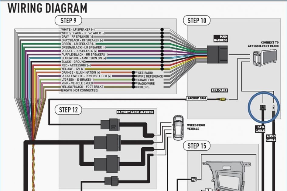
An Aftermarket Radio Wiring Diagram outlines the electrical connections required for installing a new radio in a vehicle. It depicts wires by color, function, and location, guiding proper connections.
Wiring diagrams ensure seamless integration, reducing the risk of short circuits or incorrect functionality. It facilitates do-it-yourself installations, empowers car enthusiasts, and promotes safety.
A significant development was the adoption of standard wire colors by the Electronic Industries Alliance (EIA) in 1975, enabling universal color coding across radio manufacturers and simplifying wiring procedures.
This article will delve into the types of wiring diagrams, proper installation techniques, and troubleshooting tips to empower readers with the knowledge necessary for successful aftermarket radio installations.
Aftermarket radio wiring diagrams provide a roadmap for installing a new car stereo, ensuring proper connections and avoiding electrical hazards. Essential aspects to consider include:
- Color Coding: Standardized wire colors simplify identification.
- Pin Configuration: Diagrams show which wires connect to specific pins on the radio.
- Power Connections: Identifying constant, switched, and ground wires is crucial.
- Speaker Outputs: Matching wire sizes and speaker impedances is essential.
- Antenna Connection: Ensure proper antenna connection for optimal radio reception.
- Accessory Inputs: Diagrams show connections for auxiliary devices like CD changers or Bluetooth modules.
- Vehicle Compatibility: Diagrams vary by vehicle make and model, ensuring compatibility.
- Troubleshooting Guide: Diagrams provide guidance for diagnosing and resolving installation issues.
- Safety Precautions: Diagrams emphasize proper grounding and fuse protection for electrical safety.
Understanding these aspects empowers DIY enthusiasts to install aftermarket radios confidently. By following wiring diagrams meticulously, they can achieve seamless integration, enhance their audio experience, and maintain vehicle safety.
Color Coding
Color coding is a critical component of aftermarket radio wiring diagrams, providing a simplified and consistent method for identifying the numerous wires involved in the installation process. By adhering to standardized color conventions, manufacturers ensure that wires serving specific functions are easily distinguishable, regardless of the vehicle make or model.
For instance, in most aftermarket radio wiring diagrams, the constant power wire is denoted by a yellow color, while the switched power wire is typically red. This color coding eliminates the need for guesswork or time-consuming trial and error, enabling installers to make quick and accurate connections. Furthermore, color coding minimizes the risk of electrical hazards by preventing incorrect wire pairings that could lead to short circuits or damage to the radio or vehicle.
The practical applications of understanding color coding in aftermarket radio wiring diagrams are immense. It empowers both professional installers and DIY enthusiasts to tackle the task with confidence, knowing that they can rely on the color scheme to guide their connections. This simplified identification process reduces installation time, minimizes the potential for errors, and ensures a seamless integration of the new radio into the vehicle’s electrical system.
In summary, color coding in aftermarket radio wiring diagrams serves as a vital tool, simplifying the identification of wires and enabling efficient and accurate installations. By adhering to standardized color conventions, manufacturers empower installers with a clear roadmap for connecting the various wires, reducing the risk of errors and ensuring the safe and proper functioning of the new car stereo.
Pin Configuration
Pin configuration is a fundamental aspect of aftermarket radio wiring diagrams. It provides a detailed roadmap for connecting the various wires to their designated pins on the radio, ensuring proper functionality and preventing electrical hazards.
-
Wire Identification
Pin configuration diagrams clearly indicate which wire corresponds to each function, such as power, ground, speakers, and antenna. This eliminates guesswork and minimizes the risk of misconnections.
-
Connector Types
Diagrams specify the type of connector used for each wire, such as spade, bullet, or RCA. Matching the correct connector ensures a secure and reliable connection.
-
Pin Locations
Diagrams provide a visual representation of the pin layout on the radio’s harness. This helps installers locate the correct pins for each wire, avoiding confusion or errors.
-
Polarity
For connections that require specific polarity, such as power and speaker wires, diagrams indicate the correct orientation to ensure proper operation and prevent damage.
Understanding pin configuration is crucial for successful aftermarket radio installations. By meticulously following the diagrams and connecting wires to their designated pins, installers can guarantee optimal performance, prevent electrical issues, and enjoy a seamless audio experience in their vehicles.
Power Connections
In the context of aftermarket radio wiring diagrams, understanding power connections is paramount. Identifying constant, switched, and ground wires ensures the proper functioning and safety of the installed radio.
-
Constant Power
This wire provides continuous power to the radio, maintaining its memory settings even when the vehicle is turned off. It typically connects to the vehicle’s battery or a constant power source.
-
Switched Power
This wire supplies power to the radio only when the vehicle’s ignition is turned on. It connects to the vehicle’s ignition switch or a switched power source.
-
Ground
This wire provides a path for electrical current to complete the circuit. It connects to the vehicle’s chassis or a dedicated ground point.
-
Wire Colors
Constant power wires are typically yellow, switched power wires are red, and ground wires are black. However, it’s essential to consult the specific wiring diagram for the vehicle and radio being installed.
Accurately identifying and connecting these wires is crucial. Incorrect connections can lead to damage to the radio or electrical system, or even pose a safety hazard. By carefully following the wiring diagram and adhering to these guidelines, installers can ensure a successful and safe aftermarket radio installation.
Speaker Outputs
When dealing with aftermarket radio wiring diagrams, correctly understanding speaker outputs, including matching wire sizes and speaker impedances, is of utmost importance. It ensures optimal audio performance, protects equipment, and prevents potential hazards.
-
Wire Gauge
Matching wire size to speaker power handling is crucial. Thinner wires can’t handle high power, leading to overheating and damage. Use thicker wires for higher power speakers.
-
Speaker Impedance
Speakers have impedance ratings (ohms). Mismatched impedance can reduce power output, distort sound, or even damage the amplifier. Match the speaker impedance to the amplifier’s output impedance.
-
Polarity
Speaker terminals have polarity (+ and -). Incorrect polarity can result in reduced sound quality or even damage to the speakers. Ensure positive and negative terminals are connected correctly.
-
Parallel vs. Series Wiring
Speakers can be wired in parallel or series to achieve different impedance and power handling. Parallel wiring lowers impedance, while series wiring increases it. Use the appropriate wiring method based on the desired impedance and power.
Understanding these aspects helps ensure proper speaker connections, maximizing audio quality, preventing damage, and guaranteeing a safe and enjoyable listening experience. By carefully following the wiring diagram and adhering to these guidelines, installers can achieve optimal performance from their aftermarket car audio systems.
Antenna Connection
In the realm of aftermarket radio wiring diagrams, antenna connection plays a crucial role in ensuring optimal radio reception. Without a proper connection, radio signals may be weak, intermittent, or nonexistent, diminishing the overall audio experience.
-
Antenna Type
Aftermarket radios are compatible with various antenna types, such as whip antennas, mast antennas, and shark fin antennas. Choosing the correct antenna for the specific vehicle and radio is essential for optimal reception.
-
Antenna Placement
The placement of the antenna on the vehicle affects signal strength and quality. Typically, antennas are mounted on the roof or trunk lid for unobstructed signal reception.
-
Antenna Connections
Antenna connections vary depending on the radio and antenna type. Common types include DIN, SMB, and F connectors. Matching the correct connector ensures a secure connection and optimal signal transfer.
-
Grounding
Proper grounding is crucial for effective antenna performance. The antenna must be grounded to the vehicle’s chassis to complete the electrical circuit and minimize interference.
By understanding and addressing these facets of antenna connection, installers can ensure a strong and reliable radio signal, enhancing the overall audio experience in their vehicles.
Accessory Inputs
Accessory inputs in aftermarket radio wiring diagrams provide a roadmap for integrating auxiliary devices such as CD changers and Bluetooth modules, expanding the functionality and entertainment options in vehicles.
-
CD Changer Compatibility
Wiring diagrams specify the connections required for CD changers, allowing users to enjoy their music collection on the go. They outline the power, ground, and control wires necessary for seamless integration.
-
Bluetooth Module Integration
Diagrams provide guidance on connecting Bluetooth modules, enabling wireless audio streaming and hands-free calling. They indicate the power, ground, and audio input/output wires for proper functionality.
-
Auxiliary Input Connections
Wiring diagrams show the connections for auxiliary input jacks, allowing users to connect external audio sources such as MP3 players or smartphones. They specify the audio input wires and any required power connections.
-
Steering Wheel Control Interface
For vehicles with steering wheel audio controls, wiring diagrams outline the connections to the steering wheel control interface module. This module translates steering wheel button presses into commands for the radio, providing convenient control while driving.
Understanding accessory inputs in aftermarket radio wiring diagrams empowers installers to integrate various auxiliary devices, enhancing the in-vehicle audio experience. By following the diagrams precisely, they can ensure proper functionality, avoid electrical issues, and maximize the entertainment capabilities of their aftermarket radios.
Vehicle Compatibility
In the realm of aftermarket radio wiring diagrams, vehicle compatibility plays a crucial role in ensuring successful and safe installations. Wiring diagrams are meticulously designed to match the specific electrical systems and configurations of different vehicle makes and models.
-
Wiring Harness Compatibility
Aftermarket radios often come with vehicle-specific wiring harnesses, pre-wired to match the color coding and pin configuration of the vehicle’s factory harness. Using the correct harness ensures a seamless connection, eliminating the need for splicing or modification.
-
Dash Kit Integration
Installing an aftermarket radio typically requires a dash kit, a custom-designed fascia that adapts the radio to the vehicle’s dashboard. Wiring diagrams provide guidance on integrating the dash kit, ensuring proper fit and finish.
-
Steering Wheel Control Interface
For vehicles with steering wheel audio controls, wiring diagrams outline the connections to the steering wheel control interface module. This module translates steering wheel button presses into commands for the radio, maintaining convenience and safety while driving.
-
Antenna Adapters
Aftermarket radios may require antenna adapters to match the vehicle’s factory antenna connection. Wiring diagrams specify the correct adapter for each vehicle, ensuring optimal radio reception.
Understanding vehicle compatibility in aftermarket radio wiring diagrams is paramount for successful installations. By carefully following the diagrams and using the appropriate components, installers can ensure a seamless integration of the new radio into the vehicle’s electrical system, unlocking its full functionality and enhancing the driving experience.
Troubleshooting Guide
Aftermarket radio wiring diagrams play a pivotal role in troubleshooting and resolving installation issues, providing a comprehensive guide for installers to identify and rectify problems efficiently. The troubleshooting guide within the wiring diagram serves as an invaluable tool, offering step-by-step instructions and diagnostic tips to address common challenges.
The cause-and-effect relationship between the troubleshooting guide and the wiring diagram is evident. Without accurate wiring, electrical issues can arise, leading to malfunctions or poor performance of the aftermarket radio. The troubleshooting guide empowers installers to pinpoint the root cause of these issues, whether it’s incorrect wire connections, faulty components, or grounding problems.
Real-life examples of the troubleshooting guide’s practical applications abound. For instance, if the radio does not power on, the guide can help installers check if the constant power wire is properly connected to the vehicle’s battery. Similarly, if speakers produce distorted sound, the guide can assist in identifying loose or damaged speaker wire connections.
Understanding the connection between the troubleshooting guide and the aftermarket radio wiring diagram is crucial for successful installations and maintenance. By leveraging the information provided in the guide, installers can diagnose and resolve issues promptly, ensuring optimal performance and longevity of the aftermarket radio system.
Safety Precautions
In the realm of aftermarket radio wiring diagrams, safety precautions hold paramount importance, ensuring the electrical integrity and well-being of both the installed equipment and the vehicle itself. These diagrams emphasize proper grounding and fuse protection, two critical aspects that safeguard against electrical hazards and potential damage.
-
Proper Grounding
Grounding provides a safe and dedicated path for electrical current to return to the vehicle’s chassis, preventing voltage spikes and potential damage to sensitive electronic components. Wiring diagrams clearly indicate the designated grounding points, ensuring proper grounding procedures.
-
Fuse Protection
Fuses act as sacrificial devices, safeguarding circuits and components from excessive electrical current. Wiring diagrams specify the appropriate fuse ratings for each circuit, preventing damage to the radio or vehicle’s electrical system in the event of a fault.
-
Avoiding Electrical Shorts
Improper wiring or loose connections can lead to electrical shorts, causing damage to components and potentially sparking electrical fires. Wiring diagrams guide installers in making secure and insulated connections, minimizing the risk of shorts and ensuring electrical safety.
-
Compliance with Codes and Standards
Wiring diagrams adhere to established electrical codes and safety standards, ensuring compliance with industry best practices. This compliance minimizes electrical hazards and promotes the longevity of the aftermarket radio installation.
Understanding and adhering to the safety precautions outlined in aftermarket radio wiring diagrams is essential for a successful and safe installation. Proper grounding, fuse protection, and careful attention to connections minimize electrical risks, protect equipment, and ensure a reliable and enjoyable audio experience in the vehicle.


Related Posts


