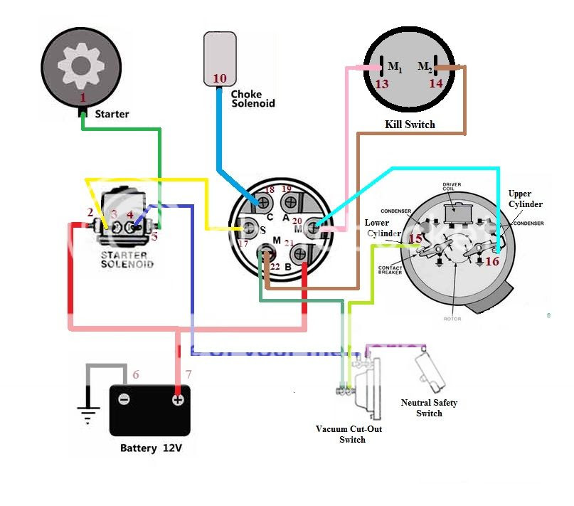
A 6 Pin Ignition Switch Wiring Diagram is a schematic diagram that outlines the electrical connections for a 6-pin ignition switch. This diagram shows which terminals on the ignition switch are connected to which components in the vehicle. An example of a 6-pin ignition switch wiring diagram is the diagram for a 1995 Chevrolet Silverado. This diagram shows that terminal 1 on the ignition switch is connected to the battery, terminal 2 is connected to the starter, terminal 3 is connected to the coil, terminal 4 is connected to the instrument panel, terminal 5 is connected to the ignition switch, and terminal 6 is connected to ground.
6 Pin Ignition Switch Wiring Diagrams are important because they allow you to understand how the ignition switch is connected to the other components in the vehicle. This information can be helpful if you are troubleshooting a problem with your vehicle’s ignition system. Additionally, 6 Pin Ignition Switch Wiring Diagrams can be used to install a new ignition switch. A key historical development in the evolution of 6 Pin Ignition Switch Wiring Diagrams is the introduction of computer-aided design (CAD). CAD software allows engineers to create detailed and accurate wiring diagrams that are easy to understand and follow.
In the following sections, we will discuss the different components of a 6 Pin Ignition Switch Wiring Diagram and how to use this information to troubleshoot and repair problems with your vehicle’s ignition system.
6 Pin Ignition Switch Wiring Diagrams are essential for understanding how to troubleshoot and repair problems with your vehicle’s ignition system. They provide a detailed overview of the electrical connections between the ignition switch and the other components in the vehicle. The following are 10 key aspects of 6 Pin Ignition Switch Wiring Diagrams:
- Terminals: The ignition switch has six terminals, each of which is connected to a different component in the vehicle.
- Connections: The wiring diagram shows how the terminals on the ignition switch are connected to the other components in the vehicle.
- Colors: The wires in the wiring diagram are color-coded to make it easy to identify which terminal they are connected to.
- Gauge: The gauge of the wire indicates the thickness of the wire. Thicker wires can handle more current than thinner wires.
- Length: The length of the wire indicates how far the wire runs from the ignition switch to the other component.
- Type: The type of wire indicates the material that the wire is made of. Copper wire is the most common type of wire used in automotive wiring.
- Function: The function of the wire indicates what the wire is used for. For example, some wires are used to carry power to the ignition switch, while other wires are used to send signals from the ignition switch to other components.
- Troubleshooting: Wiring diagrams can be used to troubleshoot problems with the ignition system. By following the wires in the diagram, you can identify which component is causing the problem.
- Repair: Wiring diagrams can be used to repair problems with the ignition system. By following the wires in the diagram, you can identify which wire needs to be replaced or repaired.
- Installation: Wiring diagrams can be used to install a new ignition switch. By following the wires in the diagram, you can ensure that the ignition switch is connected correctly.
These are just a few of the key aspects of 6 Pin Ignition Switch Wiring Diagrams. By understanding these aspects, you can use wiring diagrams to troubleshoot, repair, and install ignition switches. For example, if you are having problems with your vehicle’s ignition system, you can use a wiring diagram to identify which component is causing the problem. Once you have identified the problem, you can use the wiring diagram to repair the component or replace it if necessary.
Terminals
In the context of a 6 Pin Ignition Switch Wiring Diagram, the terminals play a crucial role in establishing electrical connections between the ignition switch and various components of the vehicle. These terminals act as connection points, allowing the ignition switch to control and distribute power to different systems.
- Battery Terminal: Connects the ignition switch to the vehicle’s battery, providing a power source for the electrical system.
- Starter Terminal: Activates the starter motor, engaging the engine’s flywheel to start the vehicle.
- Coil Terminal: Supplies power to the ignition coil, which generates the high voltage required for spark plug ignition.
- Instrument Panel Terminal: Transmits signals to the instrument panel, providing information such as engine speed and fuel level.
Understanding the functions of these terminals is essential for troubleshooting and repairing ignition system issues. By tracing the connections from each terminal in the wiring diagram, technicians can identify faulty components or damaged wires, enabling accurate diagnostics and efficient repairs.
Connections
In the context of a 6 Pin Ignition Switch Wiring Diagram, the connections between the ignition switch terminals and other vehicle components are of paramount importance. These connections establish the pathways for electrical current to flow, enabling the ignition switch to control and distribute power throughout the vehicle’s systems. Understanding these connections is critical for troubleshooting, repairing, and installing ignition switch systems.
The wiring diagram serves as a roadmap, visually representing the connections between the ignition switch terminals and other components. By tracing the connections in the diagram, technicians can identify the specific wires and terminals involved in each circuit. This information allows them to pinpoint faults, such as broken wires, loose connections, or faulty components.
Real-life examples of these connections in a 6 Pin Ignition Switch Wiring Diagram include the following:
- The connection between the battery terminal and the starter terminal provides power to engage the starter motor and crank the engine.
- The connection between the coil terminal and the distributor terminal supplies voltage to the ignition coil, which generates the high-voltage spark required for ignition.
- The connection between the instrument panel terminal and the fuel gauge terminal transmits signals to the instrument panel, providing the driver with real-time information about the fuel level.
By understanding these connections and their functions, technicians can effectively diagnose and resolve ignition system issues, ensuring the vehicle operates safely and reliably.
Colors
In the context of a 6 Pin Ignition Switch Wiring Diagram, color-coding plays a critical role in facilitating efficient and accurate wiring installations and troubleshooting. The color-coding of wires establishes a standardized system, allowing technicians and enthusiasts to quickly identify the function and destination of each wire, simplifying the process of tracing connections and resolving electrical issues.
Real-life examples of color-coding in a 6 Pin Ignition Switch Wiring Diagram include:
- Red wires typically indicate power connections, such as the wire connecting the battery terminal to the starter terminal.
- Black wires often represent ground connections, providing a return path for electrical current.
- Blue wires may be used for ignition-related connections, such as the wire connecting the coil terminal to the distributor terminal.
Understanding the color-coding scheme of a 6 Pin Ignition Switch Wiring Diagram provides several practical benefits:
- Simplified Installation: Color-coding allows technicians to quickly identify which wires need to be connected to each terminal, reducing the risk of incorrect connections and ensuring proper functionality.
- Efficient Troubleshooting: By tracing the color-coded wires, technicians can easily pinpoint the source of electrical problems, such as shorts, broken connections, or faulty components.
- Enhanced Safety: Correctly identifying and connecting wires based on their color-coding helps prevent electrical hazards, such as fires or damage to sensitive electronic components.
In summary, the color-coding of wires in a 6 Pin Ignition Switch Wiring Diagram serves as a valuable tool for technicians and enthusiasts alike. It simplifies wiring installations, expedites troubleshooting, and enhances safety, making it an indispensable element of any informative or instructional content on this topic.
Gauge
In the context of a 6 Pin Ignition Switch Wiring Diagram, the gauge of the wire plays a crucial role in ensuring the proper functioning of the ignition system. The gauge refers to the thickness or cross-sectional area of the wire, which directly affects its current-carrying capacity. Thicker wires, with a larger cross-sectional area, can handle higher electrical currents than thinner wires, which have a smaller cross-sectional area.
Within a 6 Pin Ignition Switch Wiring Diagram, different wires are assigned specific gauges based on the amount of current they need to carry. For instance, the wire connecting the battery terminal to the starter terminal typically uses a thicker gauge wire to accommodate the high current required to engage the starter motor. Conversely, wires carrying signals or low-power currents, such as those connected to the instrument panel, may use thinner gauge wires.
Understanding the relationship between wire gauge and current-carrying capacity is essential for accurate wiring installations and troubleshooting. Using wires with an appropriate gauge ensures that the electrical system operates safely and efficiently. Incorrect wire gauge selection can lead to various issues, such as voltage drop, overheating, or even electrical fires.
In summary, the gauge of the wire is a critical component of a 6 Pin Ignition Switch Wiring Diagram as it determines the wire’s ability to handle electrical current. Proper selection and use of wire gauges are crucial for ensuring the reliable and safe operation of the ignition system and the vehicle as a whole.
Length
Within the context of “6 Pin Ignition Switch Wiring Diagram”, the length of the wire holds significant importance as it directly affects the functionality and performance of the ignition system. Understanding the length of each wire helps ensure proper installation, troubleshooting, and maintenance of the vehicle’s electrical components.
- Wire Management: The length of the wire determines how it is routed and managed within the vehicle. Proper wire management prevents tangles, reduces stress on connections, and ensures optimal airflow for cooling.
- Voltage Drop: Longer wires have a higher resistance, which can lead to voltage drop over the length of the wire. This voltage drop can affect the performance of the connected components, especially those requiring precise voltage regulation.
- Signal Integrity: For wires carrying signals, such as those connected to sensors or electronic control units, the length of the wire can impact signal integrity. Longer wires may introduce signal distortion or attenuation, affecting the accuracy and reliability of the transmitted signals.
- Circuit Protection: The length of the wire can influence the choice of circuit protection devices, such as fuses or circuit breakers. Longer wires may require higher-rated protection devices to ensure adequate protection against overcurrent conditions.
In summary, the length of the wire in a “6 Pin Ignition Switch Wiring Diagram” is a crucial factor that needs to be carefully considered during installation, troubleshooting, and maintenance. Understanding the implications of wire length helps ensure the proper functioning of the ignition system and the overall reliability of the vehicle’s electrical system.
Type
In the context of “6 Pin Ignition Switch Wiring Diagram”, the type of wire used is a critical component influencing the overall functionality and reliability of the ignition system. The most common type of wire employed in automotive wiring, including ignition switch wiring diagrams, is copper wire. Copper possesses excellent electrical conductivity, making it ideal for transmitting electrical current with minimal resistance. Additionally, copper’s malleability allows for easy routing and shaping, facilitating the creation of complex wiring configurations.
The selection of copper wire as the primary material for ignition switch wiring diagrams is attributed to its superior electrical properties. Copper’s high conductivity ensures efficient current flow, minimizing voltage drop and power loss over the length of the wire. This is particularly important in ignition systems, where precise voltage levels are crucial for proper ignition timing and engine performance. Moreover, copper’s resistance to corrosion and oxidation contributes to the long-term reliability of the wiring system, reducing the likelihood of electrical faults or interruptions.
Real-life examples of “Type: The type of wire indicates the material that the wire is made of. Copper wire is the most common type of wire used in automotive wiring.” within “6 Pin Ignition Switch Wiring Diagram” include:
- The wire connecting the battery terminal to the starter solenoid is typically made of thicker copper wire to accommodate the high current required during engine cranking.
- Thinner copper wire is used for signal transmission, such as the wire connecting the ignition switch to the instrument panel, to minimize electrical interference and ensure accurate signal transmission.
- Copper wire with insulation and shielding is employed in applications where electrical noise or electromagnetic interference needs to be minimized, ensuring reliable signal integrity.
Understanding the relationship between “Type: The type of wire indicates the material that the wire is made of. Copper wire is the most common type of wire used in automotive wiring.” and “6 Pin Ignition Switch Wiring Diagram” is crucial for proper installation, maintenance, and troubleshooting of automotive electrical systems. By selecting the appropriate type of wire based on its material properties, electrical requirements, and environmental conditions, technicians can ensure the safe and efficient operation of the ignition system.
Function
Within the context of a “6 Pin Ignition Switch Wiring Diagram”, the function of each wire plays a critical role in ensuring the proper operation and functionality of the ignition system. The function of the wire determines its specific purpose, whether it is to carry power, transmit signals, or perform other electrical tasks within the ignition system.
Understanding the function of each wire is essential for accurate installation, maintenance, and troubleshooting of the ignition system. Misidentification or incorrect connection of wires can lead to electrical faults, component damage, or even safety hazards. The “6 Pin Ignition Switch Wiring Diagram” provides a clear representation of the functions assigned to each wire, enabling technicians and enthusiasts to easily identify and trace the flow of electrical current.
Real-life examples of the function of wires within a “6 Pin Ignition Switch Wiring Diagram” include:
- The wire connected to the battery terminal provides power to the ignition switch, allowing it to control the ignition system.
- The wire connected to the starter terminal carries a high current to engage the starter motor and crank the engine.
- The wire connected to the coil terminal supplies voltage to the ignition coil, which generates the high-voltage spark required for ignition.
- The wire connected to the instrument panel terminal transmits signals to the instrument cluster, providing information such as engine speed and fuel level.
In summary, the “Function: The function of the wire indicates what the wire is used for. For example, some wires are used to carry power to the ignition switch, while other wires are used to send signals from the ignition switch to other components.” is a critical aspect of a “6 Pin Ignition Switch Wiring Diagram”. Understanding the function of each wire enables proper installation, maintenance, and troubleshooting, ensuring the reliable operation of the ignition system and the vehicle as a whole.
Troubleshooting
Within the context of “6 Pin Ignition Switch Wiring Diagram”, troubleshooting plays a crucial role in identifying and resolving electrical issues within the ignition system. By utilizing the wiring diagram as a guide, technicians can systematically trace the flow of electrical current and pinpoint the source of any malfunctions.
- Identifying Faulty Components: Wiring diagrams allow technicians to identify faulty components by tracing the electrical connections and measuring voltage, resistance, or continuity at specific points in the circuit. This helps isolate the problematic component and facilitate targeted repairs.
- Tracing Electrical Faults: Wiring diagrams serve as a roadmap for tracing electrical faults, such as short circuits, open circuits, or ground faults. By following the wires in the diagram, technicians can locate the exact point of failure and determine the appropriate repair strategy.
- Analyzing Circuit Behavior: Wiring diagrams enable technicians to analyze the behavior of electrical circuits under different operating conditions. This helps them predict potential issues, optimize circuit performance, and identify areas for improvement.
- Real-Life Examples: In practice, troubleshooting using wiring diagrams is essential for resolving various ignition system problems. For instance, tracing the wire from the ignition switch to the starter solenoid can help identify a faulty starter switch or a broken wire causing a no-crank condition.
In conclusion, the ability to troubleshoot using wiring diagrams is a valuable skill for maintaining and repairing ignition systems. By understanding the function and connections of each wire, technicians can efficiently diagnose and resolve electrical issues, ensuring the reliable operation of vehicles and minimizing downtime.
Repair
Within the context of “6 Pin Ignition Switch Wiring Diagram”, the aspect of “Repair” holds significant importance as it equips technicians and enthusiasts with the knowledge and guidance to restore a faulty ignition system to proper functionality.
- Identifying Faulty Wires: By tracing the wires in the wiring diagram, technicians can pinpoint damaged, broken, or loose wires that disrupt the flow of electrical current within the ignition system.
- Replacing Damaged Wires: Once faulty wires are identified, the wiring diagram serves as a guide for replacing them with new wires of the correct gauge, type, and length, ensuring proper electrical connections.
- Repairing Wire Connections: In cases where wires are not completely broken but have loose or corroded connections, the wiring diagram helps technicians locate these points and perform repairs, such as soldering or crimping, to restore electrical continuity.
- Troubleshooting Complex Issues: For complex electrical issues that involve multiple components and wires, the wiring diagram acts as a roadmap, aiding in the systematic diagnosis and repair of the ignition system, minimizing downtime and ensuring efficient troubleshooting.
In conclusion, the ability to repair ignition system issues using wiring diagrams empowers technicians with the necessary knowledge and tools to effectively resolve electrical faults, ensuring the reliable operation of vehicles and preventing potential hazards.
Installation
Within the context of “6 Pin Ignition Switch Wiring Diagram”, the aspect of “Installation” serves as a crucial component, providing clear instructions and guidance for technicians and enthusiasts undertaking the task of installing a new ignition switch. This section of the wiring diagram outlines the proper procedures for connecting the wires to the ignition switch, ensuring that the electrical system functions correctly.
The “6 Pin Ignition Switch Wiring Diagram” acts as a roadmap, visually representing the connections between the ignition switch terminals and the vehicle’s electrical components. By following the wires in the diagram, installers can identify the correct wire for each terminal, ensuring that the ignition switch is wired according to the manufacturer’s specifications.
Real-life examples of “Installation: Wiring diagrams can be used to install a new ignition switch. By following the wires in the diagram, you can ensure that the ignition switch is connected correctly.” within “6 Pin Ignition Switch Wiring Diagram” include:
- When replacing a faulty ignition switch in a vehicle, the wiring diagram guides the technician in connecting the wires to the new switch, ensuring that the starter motor, ignition coil, and other components receive the appropriate electrical signals.
- In custom vehicle builds or modifications, the wiring diagram is essential for installing an aftermarket ignition switch, allowing the installer to integrate the new switch into the existing electrical system.
Understanding the connection between “Installation: Wiring diagrams can be used to install a new ignition switch. By following the wires in the diagram, you can ensure that the ignition switch is connected correctly.” and “6 Pin Ignition Switch Wiring Diagram” is crucial for successful ignition switch installations. By utilizing the wiring diagram as a reference, technicians and enthusiasts can minimize the risk of incorrect connections, electrical faults, and potential safety hazards, ensuring the reliable operation of the vehicle’s ignition system.


Related Posts


