A 1/4 Stereo Jack Wiring Diagram represents the electrical connections for a 3-conductor stereo jack, commonly used in audio applications. It defines the signal paths and ground connections to transmit stereo audio signals.
Essential in audio equipment, this wiring diagram enables the proper transmission of audio signals between devices such as guitars, amplifiers, mixers, and recording interfaces. Its standardized configuration ensures compatibility and reliable signal transmission, making it a crucial component in audio setups.
Let us delve deeper into the intricacies of a 1/4 Stereo Jack Wiring Diagram, examining its components, connection protocols, and the captivating world of audio engineering.
Understanding the essential aspects of a 1/4 Stereo Jack Wiring Diagram is paramount for effectively utilizing this crucial component in audio setups. Here, we explore nine key aspects that encompass the significance, functionality, and application of this wiring diagram:
- Connector Type: TRS (Tip-Ring-Sleeve) or TS (Tip-Sleeve), determining signal transmission capabilities (stereo or mono).
- Signal Paths: Defines the paths for left and right audio channels, ensuring proper signal routing.
- Ground Connection: Provides a common reference point for audio signals, reducing noise and interference.
- Compatibility: Ensures seamless connection between devices with matching jack configurations.
- Audio Quality: Proper wiring practices maintain signal integrity, optimizing audio quality.
- Durability: Robust construction withstands frequent use and ensures reliable performance.
- Versatility: Supports a wide range of audio applications, including guitars, keyboards, mixers, and more.
- Standardization: Adherence to industry standards ensures consistent performance and compatibility.
- Troubleshooting: Wiring diagrams aid in identifying and resolving connection issues, ensuring optimal audio performance.
These aspects collectively contribute to the effectiveness and versatility of 1/4 Stereo Jack Wiring Diagrams. Understanding them enables proper implementation, maintenance, and troubleshooting, ensuring seamless audio signal transmission in countless applications.
Connector Type
In the realm of 1/4 Stereo Jack Wiring Diagrams, the connector type plays a pivotal role in determining the signal transmission capabilities of the jack. Understanding the distinction between TRS (Tip-Ring-Sleeve) and TS (Tip-Sleeve) connectors is essential for achieving optimal audio performance.
-
TRS Connectors:
TRS connectors, featuring three conductors (tip, ring, sleeve), are designed for stereo signal transmission. Each conductor carries a separate audio channel (left and right), while the sleeve serves as the common ground reference. TRS connectors are commonly found in stereo audio applications, such as guitars, keyboards, and mixers.
-
TS Connectors:
TS connectors, with two conductors (tip, sleeve), are used for mono signal transmission. They carry a single audio channel (mono) on the tip conductor, while the sleeve serves as the ground reference. TS connectors are frequently employed in guitar setups and unbalanced audio applications.
The choice between TRS and TS connectors depends on the desired signal transmission configuration. Stereo applications, requiring separate left and right audio channels, necessitate TRS connectors. Conversely, mono applications, where only a single audio channel is needed, can utilize TS connectors. Proper selection and wiring of the appropriate connector type ensure accurate signal transmission and optimal audio performance.
Signal Paths
In the intricate world of 1/4 Stereo Jack Wiring Diagrams, signal paths hold paramount importance, ensuring the seamless transmission of stereo audio signals. These diagrams define the electrical pathways for both left and right audio channels, guaranteeing proper signal routing and accurate sound reproduction.
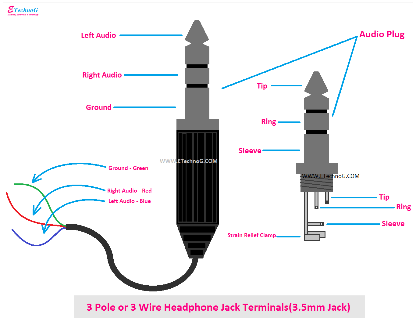
- Conductor Configuration: TRS (Tip-Ring-Sleeve) connectors, commonly employed in stereo applications, feature three conductors. The tip carries the left audio channel, the ring carries the right audio channel, and the sleeve serves as the common ground reference.
- Left and Right Channel Differentiation: Proper wiring practices distinguish between the left and right audio channels, ensuring that the left channel signal is routed to the left speaker and the right channel signal to the right speaker, creating a stereo soundscape.
- Signal Integrity: Meticulous attention to signal path design minimizes signal loss and interference, preserving the integrity of the audio signal from source to destination.
- Balanced vs. Unbalanced Signals: Signal paths can accommodate both balanced and unbalanced signals. TRS connectors support balanced signals, which are less susceptible to noise and interference, while TS connectors handle unbalanced signals.
Understanding signal paths in 1/4 Stereo Jack Wiring Diagrams is crucial for achieving optimal audio performance. By ensuring proper signal routing and maintaining signal integrity, these diagrams lay the foundation for high-quality stereo audio transmission in a multitude of applications, from home audio systems to professional recording studios.
Ground Connection
Within the intricate realm of 1/4 Stereo Jack Wiring Diagrams, the ground connection stands as a cornerstone, playing a pivotal role in ensuring pristine audio signal transmission. Its function is to establish a common reference point for audio signals, effectively minimizing noise and interference, thereby preserving signal integrity and enhancing overall audio performance.
The ground connection serves as a crucial component of the 1/4 Stereo Jack Wiring Diagram, providing a stable electrical pathway for audio signals to return to their source. Without a proper ground connection, audio signals can become corrupted by unwanted noise and interference, resulting in audible distortions, hums, and buzzes.
In real-life applications, the ground connection in a 1/4 Stereo Jack Wiring Diagram manifests in various forms. In balanced audio setups, the ground connection is typically achieved through a third conductor within the TRS connector, ensuring equal and opposite signal paths for both the positive and negative audio signals. In unbalanced setups, the ground connection is commonly established through the sleeve of the TS connector.
Understanding the significance of the ground connection in 1/4 Stereo Jack Wiring Diagrams is paramount for achieving optimal audio performance. Proper grounding techniques not only reduce noise and interference but also safeguard audio equipment from potential damage caused by ground loops and other electrical hazards.
In summary, the ground connection in a 1/4 Stereo Jack Wiring Diagram serves as an essential element for maintaining signal integrity and minimizing noise. Its proper implementation is crucial for achieving high-quality audio transmission in various applications, ranging from home audio systems to professional recording studios.
Compatibility
Within the realm of 1/4 Stereo Jack Wiring Diagrams, compatibility stands as a cornerstone, ensuring seamless connectivity and optimal performance between devices equipped with matching jack configurations. This compatibility encompasses various facets, each contributing to the successful transmission of audio signals and the creation of immersive audio experiences.
- Standardized Jack Dimensions: 1/4 Stereo Jack Wiring Diagrams adhere to industry-established standards for jack dimensions, ensuring a universal fit across devices. This standardization allows for effortless interchangeability of cables and devices, regardless of manufacturer or model.
- Matching Connector Types: Compatibility extends to the matching of connector types, such as TRS (Tip-Ring-Sleeve) for stereo signals and TS (Tip-Sleeve) for mono signals. Proper matching ensures that the correct signal paths are established, preventing signal loss or distortion.
- Electrical Compatibility: Beyond physical compatibility, 1/4 Stereo Jack Wiring Diagrams also ensure electrical compatibility between devices. This includes matching impedance levels and signal voltage ranges, guaranteeing efficient signal transfer and minimizing noise and interference.
The compatibility provided by 1/4 Stereo Jack Wiring Diagrams extends beyond technical specifications. It fosters a seamless ecosystem of audio devices, enabling musicians, audio engineers, and music enthusiasts to connect and collaborate effortlessly. This compatibility empowers creativity and innovation, allowing for the exploration of new sonic possibilities and the realization of exceptional audio experiences.
Audio Quality
In the realm of “1/4 Stereo Jack Wiring Diagram”, the aspect of “Audio Quality: Proper wiring practices maintain signal integrity, optimizing audio quality” holds immense significance. It encapsulates the critical role of meticulous wiring practices in preserving the purity and fidelity of audio signals, resulting in exceptional sonic experiences. To delve deeper into this multifaceted aspect, let’s explore four key facets that contribute to maintaining signal integrity and optimizing audio quality:
-
Proper Shielding:
Effective shielding of audio cables and connectors is paramount in preventing electromagnetic interference (EMI) and radio frequency interference (RFI) from infiltrating the signal path. This shielding ensures that the audio signal remains uncorrupted by external noise, preserving its clarity and integrity.
-
High-Quality Conductors:
The choice of conductors used in the wiring plays a crucial role in maintaining signal integrity. High-quality conductors, such as oxygen-free copper or silver-plated copper, minimize resistance and capacitance, reducing signal loss and ensuring accurate transmission of audio frequencies.
-
Soldering Techniques:
Proper soldering techniques are essential for creating secure and reliable connections. Cold solder joints or insufficient solder can lead to increased resistance and signal degradation. Meticulous soldering ensures optimal current flow and maintains signal integrity throughout the wiring.
-
Grounding and Isolation:
Establishing a proper ground reference and isolating the signal paths from external noise sources are crucial for minimizing hum and noise. Proper grounding provides a stable reference point for the audio signal, while isolation prevents unwanted currents from entering the signal path, ensuring a clean and noise-free audio experience.
By adhering to proper wiring practices and paying attention to these key facets, audio professionals can ensure that their 1/4 Stereo Jack Wiring Diagrams translate into high-quality audio transmission, delivering pristine and immersive sonic experiences to listeners and music enthusiasts alike.
Durability
In the realm of “1/4 Stereo Jack Wiring Diagram”, durability stands as a cornerstone, ensuring reliable performance and longevity in the face of rigorous use. The robust construction of these wiring diagrams plays a pivotal role in maintaining signal integrity, preventing malfunctions, and ensuring uninterrupted audio transmission in demanding environments.
The durability of 1/4 Stereo Jack Wiring Diagrams is achieved through meticulous attention to detail in every aspect of their design. High-quality materials, such as durable plastics and corrosion-resistant metals, are employed to withstand the rigors of frequent use and exposure to various environmental conditions.
Real-life examples abound where the durability of 1/4 Stereo Jack Wiring Diagrams proves its worth. In professional audio setups, where cables and connectors are subjected to constant handling and movement, robust wiring diagrams ensure reliable signal transmission, preventing audio dropouts or distortions that could disrupt performances or recordings.
Understanding the critical connection between durability and 1/4 Stereo Jack Wiring Diagrams empowers audio professionals to make informed decisions when selecting and using these essential components. By opting for durable wiring diagrams, they can safeguard their audio systems against potential failures and ensure optimal performance in even the most demanding applications.
Versatility
Within the realm of “1/4 Stereo Jack Wiring Diagram”, the aspect of versatility emerges as a defining characteristic, enabling these diagrams to cater to a diverse spectrum of audio applications. This versatility stems from the inherent adaptability and compatibility of 1/4 Stereo Jack connectors, which facilitate seamless integration with various audio devices and systems.
-
Compatibility with Instruments:
1/4 Stereo Jack Wiring Diagrams are extensively used in connecting electric guitars, bass guitars, keyboards, and other musical instruments to amplifiers, effects pedals, and audio interfaces. This compatibility allows musicians to create complex signal chains and explore a wide range of sonic possibilities.
-
Integration with Mixers and Consoles:
1/4 Stereo Jack Wiring Diagrams play a crucial role in professional audio setups, enabling the connection of microphones, instruments, and other audio sources to mixers and consoles. This versatility empowers audio engineers to route and mix multiple audio signals, creating complex soundscapes and live performances.
-
Home Audio Applications:
1/4 Stereo Jack Wiring Diagrams are also prevalent in home audio systems, allowing for the connection of CD players, cassette decks, and turntables to amplifiers and speakers. This versatility enables music enthusiasts to enjoy high-quality audio playback in their personal spaces.
-
Interfacing with Audio Interfaces:
In the realm of digital audio production, 1/4 Stereo Jack Wiring Diagrams are essential for connecting instruments, microphones, and other audio sources to audio interfaces. This versatility empowers producers and recording engineers to capture and process audio signals using computers and digital audio workstations.
The versatility of 1/4 Stereo Jack Wiring Diagrams extends beyond these specific applications, reaching into various domains of audio engineering and music production. Their adaptability and compatibility make them indispensable components in the creation, manipulation, and enjoyment of audio across a multitude of platforms and devices.
Standardization
Within the realm of “1/4 Stereo Jack Wiring Diagram”, the significance of standardization cannot be overstated. Adherence to industry standards is a cornerstone that ensures consistent performance and compatibility, enabling seamless integration and reliable operation across a vast array of audio devices and systems.
Standardization plays a pivotal role in establishing uniform specifications for 1/4 Stereo Jack connectors and wiring configurations. By conforming to these standards, manufacturers can guarantee that their products will work seamlessly with other compliant devices, regardless of brand or model. This interchangeability fosters a diverse ecosystem of compatible audio equipment, empowering musicians, audio engineers, and music enthusiasts to connect and collaborate effortlessly.
Real-life examples abound where standardization proves its worth. In professional recording studios, where numerous audio devices and instruments are interconnected, standardized 1/4 Stereo Jack Wiring Diagrams ensure seamless signal flow and eliminate compatibility issues. This standardization allows engineers to focus on capturing and mixing pristine audio, confident that their equipment will perform as expected.
Beyond professional settings, standardization also benefits home audio enthusiasts. By adhering to industry standards, manufacturers can deliver affordable and high-quality audio components that are compatible with a wide range of home audio systems. This standardization empowers consumers to build customized audio setups, mixing and matching components from different brands to create their desired listening experience.
Understanding the critical connection between standardization and 1/4 Stereo Jack Wiring Diagrams is essential for anyone involved in audio production, engineering, or enjoyment. By embracing standardized practices, we unlock a world of seamless connectivity, consistent performance, and limitless creative possibilities.
Troubleshooting
In the realm of “1/4 Stereo Jack Wiring Diagram”, troubleshooting emerges as a critical component, enabling the identification and resolution of connection issues that can plague audio setups. Wiring diagrams serve as invaluable tools, providing a visual roadmap that guides users in diagnosing and rectifying these issues, ensuring optimal audio performance.
The connection between troubleshooting and 1/4 Stereo Jack Wiring Diagrams is a symbiotic one. Wiring diagrams empower users to trace signal paths, identify faulty connections, and pinpoint the root cause of audio problems. By deciphering the layout and configuration of the wiring diagram, users can systematically eliminate potential issues, such as incorrect cable connections, grounding problems, or damaged components.
Real-life examples abound where troubleshooting and wiring diagrams go hand in hand. In a professional recording studio, a faulty connection in a patch bay can lead to intermittent audio dropouts or signal degradation. By consulting the wiring diagram, the audio engineer can quickly identify the affected connection points and resolve the issue, ensuring seamless audio flow during critical recording sessions.
The practical applications of understanding the connection between troubleshooting and 1/4 Stereo Jack Wiring Diagrams extend beyond professional setups. Home audio enthusiasts can leverage wiring diagrams to diagnose and fix issues with their home stereo systems, improving sound quality and enhancing their listening experience.
In summary, troubleshooting plays a pivotal role in maintaining optimal audio performance, and 1/4 Stereo Jack Wiring Diagrams are indispensable tools in this process. By empowering users to identify and resolve connection issues, wiring diagrams ensure the integrity of audio signals, resulting in pristine sound reproduction across a wide range of applications.


Related Posts


