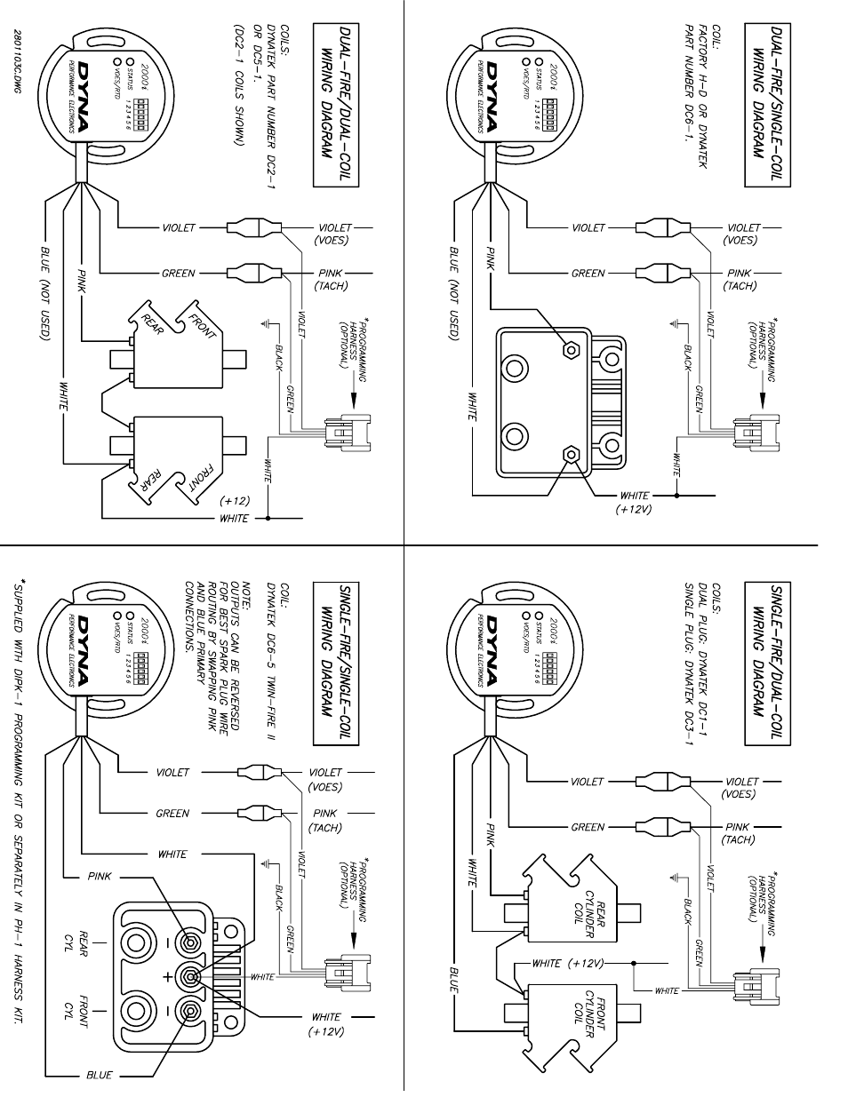
Dyna 2000 Ignition Wiring Diagram defines the electrical connections for the Dyna 2000 electronic ignition system used in Harley-Davidson motorcycles. It outlines the wiring connections between the ignition module, coil, spark plugs, and other components, ensuring proper spark timing and engine operation.
The wiring diagram is essential for troubleshooting ignition problems, modifying the ignition system, or installing aftermarket components. It allows technicians and enthusiasts to understand the system’s electrical layout and diagnose faults by tracing voltage and signal paths.
The Dyna 2000 ignition system, introduced in 1999, replaced the previous points-based ignition systems. The electronic ignition offered improved reliability, reduced maintenance, and more precise spark timing, contributing to better engine performance and fuel efficiency. The wiring diagram remains an essential tool for servicing and maintaining these motorcycles.
The Dyna 2000 Ignition Wiring Diagram is a crucial document that defines the electrical connections for the Dyna 2000 electronic ignition system used in Harley-Davidson motorcycles. Understanding its key aspects is essential for troubleshooting, modifying, or servicing the ignition system.
- Components: The wiring diagram identifies all the components of the ignition system, including the ignition module, coil, spark plugs, and associated wiring.
- Connections: It outlines the specific electrical connections between the components, ensuring proper flow of voltage and signals.
- Color Coding: The diagram typically uses color-coded wires to simplify identification and tracing.
- Grounding: It specifies the grounding points for the ignition system, which are essential for proper electrical operation.
- Testing: The wiring diagram can guide technicians in performing electrical tests to diagnose faults and verify system functionality.
- Installation: It provides instructions for installing or replacing ignition system components, ensuring correct wiring.
- Troubleshooting: The diagram helps identify potential failure points and trace electrical issues.
- Modifications: It serves as a reference for modifying the ignition system, such as installing aftermarket components or upgrading the system.
- Maintenance: The wiring diagram aids in regular maintenance tasks, such as spark plug replacement and electrical inspections.
These aspects provide a comprehensive understanding of the Dyna 2000 Ignition Wiring Diagram and its vital role in the motorcycle’s ignition system. By utilizing the diagram, technicians and enthusiasts can ensure proper ignition operation, diagnose problems, and perform modifications with confidence.
Components
The “Components: The wiring diagram identifies all the components of the ignition system, including the ignition module, coil, spark plugs, and associated wiring.” statement is a critical aspect of the “Dyna 2000 Ignition Wiring Diagram” because it defines the essential elements of the ignition system and their interconnections. The wiring diagram serves as a blueprint for the system, outlining the specific components and their electrical connections.
The ignition system’s proper function relies on the accurate identification and connection of these components. The ignition module controls the timing and delivery of spark to the spark plugs. The coil generates the high voltage required to create the spark. The spark plugs ignite the air-fuel mixture in the engine’s cylinders. The associated wiring provides the electrical pathways for these components to communicate and function.
Understanding the components and their connections is essential for troubleshooting ignition problems, performing maintenance, or modifying the system. The wiring diagram allows technicians and enthusiasts to trace electrical signals, identify faulty components, and ensure proper system operation.
Connections
Electrical connections are the backbone of the Dyna 2000 Ignition Wiring Diagram, defining the pathways for voltage and signals to flow throughout the ignition system. Without proper connections, the system cannot function effectively, leading to ignition problems, engine performance issues, and potential safety hazards.
-
Wiring Harness
The wiring harness is a bundle of wires that connects all the ignition system components. It provides a structured and organized framework for the electrical connections, ensuring proper voltage distribution and signal transmission.
-
Connectors
Connectors are used to join different sections of the wiring harness and connect specific components. They ensure a secure and reliable electrical connection, preventing loose or intermittent contacts.
-
Grounding
Grounding is essential for completing the electrical circuit and providing a reference point for voltage. The wiring diagram specifies the grounding points, which are typically connected to the motorcycle’s frame or engine.
-
Signal Transmission
The wiring diagram also outlines the paths for signal transmission between the ignition module and other components, such as the crankshaft position sensor. These signals are crucial for the ignition module to determine the correct timing and sequence of spark delivery.
Overall, the “Connections: It outlines the specific electrical connections between the components, ensuring proper flow of voltage and signals.” aspect of the Dyna 2000 Ignition Wiring Diagram is critical for maintaining a functional and reliable ignition system. By understanding and following the wiring diagram’s specifications, technicians and enthusiasts can ensure proper electrical connections, diagnose problems, and make modifications with confidence.
Color Coding
Within the Dyna 2000 Ignition Wiring Diagram, color coding plays a vital role in simplifying the identification and tracing of wires, enhancing the overall usability and functionality of the diagram. This color coding is a critical component, as it provides a standardized method for distinguishing between different wires and their corresponding functions within the ignition system.
Each wire in the wiring diagram is assigned a specific color, which remains consistent throughout the entire system. This color coding allows technicians and enthusiasts to quickly identify the purpose of each wire, reducing the risk of errors during installation, maintenance, or troubleshooting. For instance, in the Dyna 2000 Ignition Wiring Diagram, red wires typically indicate power supply, black wires represent ground connections, and blue wires are commonly used for signal transmission.
The practical applications of understanding color coding within the Dyna 2000 Ignition Wiring Diagram are numerous. Firstly, it enables efficient troubleshooting, as technicians can easily trace wires to identify potential faults or disruptions in the electrical system. Secondly, color coding facilitates modifications and upgrades to the ignition system, allowing enthusiasts to confidently add or replace components while ensuring proper connectivity.
In summary, the color coding used in the Dyna 2000 Ignition Wiring Diagram serves as an essential tool for understanding, maintaining, and modifying the ignition system. By assigning specific colors to different wires, the diagram simplifies identification and tracing, reducing the likelihood of errors and enhancing the overall functionality of the ignition system.
Grounding
Within the Dyna 2000 Ignition Wiring Diagram, grounding holds paramount importance in ensuring the proper functioning of the ignition system. Grounding refers to the establishment of an electrical connection between a circuit and a reference point, usually the motorcycle’s frame or engine, which serves as a common ground for all electrical components. This electrical connection provides a path for the completion of electrical circuits, allowing current to flow and enabling the ignition system to operate effectively.
-
Grounding Points
Grounding points are the specific locations where electrical connections are made to the motorcycle’s frame or engine. These points are carefully chosen to ensure a secure and low-resistance connection, minimizing voltage drops and ensuring proper current flow.
-
Electrical Circuit Completion
Grounding completes the electrical circuit by providing a path for current to return to the power source. Without proper grounding, the circuit remains incomplete, preventing the flow of current and hindering the ignition system’s operation.
-
Voltage Stability
Proper grounding helps maintain stable voltage levels throughout the ignition system. A good ground connection minimizes voltage fluctuations and ensures that electrical components receive the correct voltage for optimal performance.
-
Electrical Noise Reduction
Grounding also plays a role in reducing electrical noise and interference within the ignition system. A proper ground path provides a low-resistance discharge point for electrical noise, preventing it from affecting sensitive electronic components and ensuring reliable ignition operation.
In summary, grounding is a critical aspect of the Dyna 2000 Ignition Wiring Diagram, ensuring the proper operation of the ignition system. By providing a path for electrical circuit completion, maintaining voltage stability, and reducing electrical noise, grounding contributes to the overall reliability, performance, and longevity of the ignition system.
Testing
Within the context of the Dyna 2000 Ignition Wiring Diagram, testing plays a crucial role in ensuring the proper operation and maintenance of the ignition system. The wiring diagram serves as a valuable guide for technicians, providing insights into the electrical connections and components, enabling them to conduct comprehensive electrical tests to diagnose faults and verify system functionality.
-
Electrical Continuity Testing
Electrical continuity testing involves using a multimeter or test light to check for a complete electrical circuit. By following the wiring diagram, technicians can identify open circuits or high-resistance connections that may hinder proper current flow within the ignition system.
-
Voltage Measurement
The wiring diagram provides reference points for voltage measurements at various components, such as the ignition coil, spark plugs, and ignition module. Technicians can use a voltmeter to measure voltage levels and compare them to specified values, identifying potential issues with power supply or component malfunctions.
-
Signal Tracing
Signal tracing involves using an oscilloscope or other diagnostic tools to track electrical signals through the wiring harness. By following the signal paths outlined in the wiring diagram, technicians can identify signal interruptions, delays, or distortions, helping pinpoint faulty components or wiring issues.
-
System Simulation
In some cases, the wiring diagram can guide technicians in simulating system conditions to test specific components or circuits. By applying controlled inputs or varying operating parameters, technicians can recreate fault scenarios and observe system responses, aiding in the diagnosis and isolation of problems.
Overall, the “Testing: The wiring diagram can guide technicians in performing electrical tests to diagnose faults and verify system functionality.” aspect of the Dyna 2000 Ignition Wiring Diagram empowers technicians with the knowledge and guidance to perform thorough electrical testing and diagnostics. By following the wiring diagram and applying appropriate testing procedures, technicians can efficiently identify and resolve ignition system issues, ensuring optimal performance and reliability.
Installation
Within the Dyna 2000 Ignition Wiring Diagram, installation instructions play a pivotal role in ensuring the proper functioning and reliability of the ignition system. These instructions provide detailed guidance for technicians and enthusiasts alike, enabling them to confidently install or replace ignition system components, ensuring correct wiring and optimal performance.
-
Component Identification
The installation instructions clearly identify each ignition system component, providing descriptions, part numbers, and specific locations within the wiring diagram. This identification simplifies the process of locating and handling components during installation or replacement.
-
Wiring Specifications
Detailed wiring specifications are provided, including wire colors, terminal connections, and routing paths. These specifications ensure that components are wired correctly, avoiding potential short circuits, open circuits, or incorrect signal transmission.
-
Connector and Terminal Information
The instructions include comprehensive information on connectors and terminals used within the ignition system. This information covers connector types, pin assignments, and proper crimping techniques, ensuring secure and reliable electrical connections.
-
Troubleshooting and Verification
In addition to installation instructions, the wiring diagram often includes troubleshooting tips and verification procedures. These guidelines help technicians identify and resolve any potential issues during installation, ensuring the system functions correctly.
By following the installation instructions outlined in the Dyna 2000 Ignition Wiring Diagram, technicians and enthusiasts can confidently perform ignition system maintenance and repairs, ensuring proper wiring and optimal performance. These instructions provide a roadmap for successful installation, reducing the risk of errors and ensuring the ignition system operates reliably and efficiently.
Troubleshooting
Within the context of the Dyna 2000 Ignition Wiring Diagram, troubleshooting plays a crucial role in maintaining optimal performance and reliability of the ignition system. The wiring diagram serves as a valuable tool for identifying potential failure points and tracing electrical issues, enabling technicians and enthusiasts to diagnose and resolve problems efficiently.
-
Component Identification
The wiring diagram provides a comprehensive overview of the ignition system’s components, including their electrical connections and relationships. This allows technicians to quickly identify potential failure points based on symptoms and observations. -
Circuit Analysis
The diagram enables the analysis of electrical circuits within the ignition system. By tracing wire paths and connections, technicians can identify open circuits, short circuits, or high-resistance connections that may disrupt proper system operation. -
Signal Tracing
The wiring diagram aids in tracing electrical signals through the ignition system’s components. This helps technicians pinpoint faulty sensors, damaged wires, or intermittent connections that may affect signal transmission and ignition timing. -
Grounding Verification
Proper grounding is critical for the ignition system’s functionality. The wiring diagram assists in verifying grounding points and connections, ensuring that components are correctly grounded to complete electrical circuits and prevent electrical noise.
Overall, the “Troubleshooting: The diagram helps identify potential failure points and trace electrical issues.” aspect of the Dyna 2000 Ignition Wiring Diagram empowers technicians and enthusiasts with the knowledge and guidance to diagnose and resolve ignition system problems effectively. By utilizing the wiring diagram, they can systematically identify failure points, analyze circuits, trace signals, and verify grounding, leading to improved system performance and reliability.
Modifications
Within the context of the Dyna 2000 Ignition Wiring Diagram, the aspect of “Modifications: It serves as a reference for modifying the ignition system, such as installing aftermarket components or upgrading the system.” holds significant importance. This aspect empowers enthusiasts and professionals to customize and enhance their ignition systems, tailoring them to specific performance requirements or personal preferences.
-
Aftermarket Ignition Coils
The wiring diagram provides insights into the compatibility and installation procedures for aftermarket ignition coils. Upgrading to high-performance coils can deliver a stronger spark, improving combustion efficiency and overall engine performance.
-
Electronic Ignition Modules
The diagram guides the installation and wiring of aftermarket electronic ignition modules. These modules offer advanced features such as adjustable ignition timing and multiple spark discharge, optimizing ignition timing for various engine modifications.
-
Ignition Wire Upgrades
The wiring diagram assists in selecting and installing upgraded ignition wires. High-quality wires with low resistance can improve spark delivery and reduce electrical interference, contributing to smoother engine operation and better fuel economy.
-
Custom Wiring Harnesses
For extensive modifications or custom installations, the wiring diagram serves as a foundation for creating custom wiring harnesses. This allows enthusiasts to adapt the ignition system to unique engine configurations or add additional electrical components.
The ability to modify the ignition system based on the Dyna 2000 Ignition Wiring Diagram opens up a wide range of possibilities for performance tuning, troubleshooting, and personalization. By understanding the electrical connections and components involved, enthusiasts can confidently make modifications to enhance the ignition system’s functionality and optimize engine performance.
Maintenance
Within the context of the Dyna 2000 Ignition Wiring Diagram, the “Maintenance: The wiring diagram aids in regular maintenance tasks, such as spark plug replacement and electrical inspections.” aspect assumes paramount importance. It empowers enthusiasts and professionals alike to perform routine maintenance procedures, ensuring the ignition system’s optimal performance and longevity.
-
Spark Plug Replacement
The wiring diagram provides clear guidance on locating and replacing spark plugs, a crucial maintenance task for ensuring proper ignition and engine efficiency. It illustrates the correct spark plug type, torque specifications, and wiring connections, reducing the risk of incorrect installation or damage.
-
Electrical Inspections
The diagram assists in conducting comprehensive electrical inspections of the ignition system. It enables technicians to visually inspect wires, connectors, and components for signs of damage, corrosion, or loose connections. Early detection of potential electrical issues helps prevent failures and ensures reliable ignition operation.
-
Wiring Harness Maintenance
The wiring diagram serves as a reference for maintaining and repairing the wiring harness, which is a critical component of the ignition system. It guides technicians in identifying and addressing issues such as frayed wires, loose connections, or damaged insulation, ensuring optimal current flow and system integrity.
-
Troubleshooting Electrical Faults
During maintenance, the wiring diagram aids in troubleshooting electrical faults within the ignition system. By following the circuit paths and component interconnections, technicians can systematically isolate and identify the source of electrical problems, facilitating efficient repairs and preventing further damage.
Overall, the “Maintenance: The wiring diagram aids in regular maintenance tasks, such as spark plug replacement and electrical inspections.” aspect of the Dyna 2000 Ignition Wiring Diagram is indispensable for maintaining a well-functioning ignition system. It empowers enthusiasts and professionals to perform routine maintenance procedures, identify potential issues, and resolve electrical faults, ensuring optimal performance, reliability, and longevity of the ignition system.


Related Posts


