The “2 Amps 1 Capacitor Wiring Diagram” refers to an electrical configuration that employs two ammeters and a capacitor. A common application is in measuring and monitoring current flow in a circuit. For instance, in industrial settings, this wiring diagram helps maintain optimal performance of motors and other electrical equipment by ensuring accurate current readings.
Its benefits include enhanced current measurement accuracy, increased circuit protection against overcurrent, and improved reliability of electrical systems. Historically, its development played a crucial role in advancing electrical engineering, enabling more efficient monitoring and control of electrical circuits.
Moving forward, this article will delve deeper into the technical aspects, applications, and advancements of the “2 Amps 1 Capacitor Wiring Diagram,” providing insights into its significance and impact on modern electrical systems.
The “2 Amps 1 Capacitor Wiring Diagram” encompasses several key aspects that contribute to its importance in electrical engineering and applications. Understanding these aspects is essential to grasp the significance and functionality of this wiring configuration.
- Electrical measurement: Accurate measurement of electrical current flow.
- Circuit protection: Overcurrent protection for electrical devices and systems.
- Power distribution: Efficient distribution of electrical power.
- Industrial applications: Monitoring and control of electrical equipment in industrial settings.
- Electrical safety: Ensuring safe operation of electrical systems.
- Circuit analysis: Troubleshooting and analysis of electrical circuits.
- Electrical engineering education: Teaching fundamental concepts of electrical circuits.
- Historical significance: Advancement of electrical engineering practices.
- Modern advancements: Integration with digital technologies.
- Future prospects: Continued development and refinement of the wiring diagram.
These aspects are interconnected and contribute to the overall functionality and significance of the “2 Amps 1 Capacitor Wiring Diagram.” For example, its role in electrical measurement and circuit protection ensures the safe and reliable operation of electrical systems. Furthermore, its historical significance and modern advancements highlight its continuous evolution and relevance in the field of electrical engineering.
Electrical measurement
Electrical measurement, particularly the accurate determination of electrical current flow, plays a pivotal role in the design and operation of electrical circuits. Precise current measurement enables engineers and technicians to monitor, control, and troubleshoot electrical systems effectively. The “2 Amps 1 Capacitor Wiring Diagram” serves as a cornerstone in achieving accurate electrical current measurement.
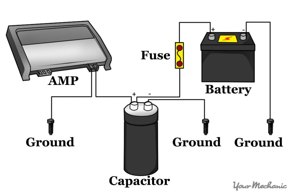
The wiring diagram employs two ammeters and a capacitor to measure current flow in a circuit. The capacitor’s presence allows for the measurement of both AC and DC currents, while the two ammeters provide redundant readings to enhance accuracy. This configuration is commonly found in industrial settings, where precise current monitoring is crucial for maintaining optimal performance and preventing equipment damage.
The practical applications of this understanding extend beyond industrial settings. In electrical engineering education, the “2 Amps 1 Capacitor Wiring Diagram” serves as a valuable tool for teaching fundamental concepts of electrical circuits and measurement techniques. Moreover, its simplicity and reliability make it a preferred choice for various electrical testing and troubleshooting scenarios.
In summary, the “2 Amps 1 Capacitor Wiring Diagram” has revolutionized electrical measurement by providing accurate and reliable current flow readings. Its significance lies in enabling efficient monitoring, control, and troubleshooting of electrical systems, contributing to the safety, reliability, and efficiency of modern electrical infrastructure.
Circuit protection
Circuit protection is a crucial aspect of “2 Amps 1 Capacitor Wiring Diagram,” ensuring the safety and longevity of electrical devices and systems. Overcurrent protection, in particular, safeguards against excessive current flow that can cause damage or even catastrophic failure.
- Fuses: Fuses are sacrificial devices that break the circuit when current exceeds a predefined threshold, preventing damage to downstream components.
- Circuit breakers: Circuit breakers are resettable devices that automatically trip when current exceeds a preset limit, allowing for quick restoration of power after the fault is cleared.
- Overcurrent relays: Overcurrent relays monitor current levels and trigger alarms or disconnect circuits when abnormal conditions are detected.
- Surge protectors: Surge protectors divert transient voltage spikes away from sensitive electronic equipment, preventing damage from overvoltage.
These overcurrent protection measures are integral to the “2 Amps 1 Capacitor Wiring Diagram,” as they ensure that any abnormal current conditions are detected and mitigated promptly. This protection extends to both AC and DC circuits, making the wiring diagram versatile and applicable in various electrical systems. Moreover, the incorporation of overcurrent protection devices enhances the reliability and safety of electrical installations, reducing the risk of electrical fires and equipment damage.
Power distribution
Power distribution plays a pivotal role in the efficient and reliable operation of electrical systems. The “2 Amps 1 Capacitor Wiring Diagram” forms an essential component of power distribution systems, enabling the effective monitoring and control of electrical current flow. The diagram incorporates mechanisms to measure, protect, and regulate current within electrical circuits, ensuring the safe and efficient distribution of electrical power.
Real-life examples of power distribution applications utilizing the “2 Amps 1 Capacitor Wiring Diagram” include industrial settings, residential buildings, and commercial complexes. In industrial environments, the wiring diagram is employed to monitor and control the power flow to heavy machinery and equipment, preventing overloads and ensuring optimal performance. Within residential and commercial buildings, it contributes to the safe and efficient distribution of electricity throughout the premises, catering to various electrical appliances and lighting systems.
The practical significance of understanding the connection between power distribution and the “2 Amps 1 Capacitor Wiring Diagram” lies in its impact on electrical system design, operation, and maintenance. Engineers and technicians rely on this understanding to ensure the safe and reliable delivery of electrical power, preventing disruptions, hazards, and equipment damage. It enables the proper sizing of electrical components, selection of appropriate protection devices, and implementation of effective monitoring strategies.
In summary, the “2 Amps 1 Capacitor Wiring Diagram” serves as a crucial tool in power distribution systems, providing accurate current measurement, protection against overcurrent conditions, and efficient power distribution. Its understanding and application are essential for the safe, reliable, and efficient operation of electrical systems in various settings.
Industrial applications
Within the realm of “2 Amps 1 Capacitor Wiring Diagram,” industrial applications hold significant importance, particularly in the monitoring and control of electrical equipment. This aspect underscores the critical role of the wiring diagram in ensuring the efficient and reliable operation of electrical systems within industrial environments.
- Equipment protection: The wiring diagram safeguards electrical equipment from overcurrent conditions, preventing damage and downtime. It employs fuses, circuit breakers, and overcurrent relays to monitor current levels and isolate faulty circuits.
- Performance monitoring: Accurate current measurement allows for real-time monitoring of equipment performance. This enables proactive maintenance and optimization of electrical systems, maximizing productivity and minimizing energy consumption.
- Energy efficiency: By precisely measuring current flow, the wiring diagram facilitates energy audits and optimization efforts. Identifying and addressing inefficient equipment or processes contributes to cost savings and environmental sustainability.
- Safety and compliance: The wiring diagram adheres to electrical safety codes and standards, ensuring compliance with regulatory requirements. It minimizes electrical hazards, preventing accidents and protecting personnel working in industrial settings.
In summary, the “2 Amps 1 Capacitor Wiring Diagram” plays a vital role in industrial applications by safeguarding equipment, monitoring performance, promoting energy efficiency, and ensuring safety and compliance. Its significance lies in enabling reliable and efficient operation of electrical systems, reducing downtime, optimizing energy consumption, and upholding safety standards in industrial environments.
Electrical safety
Within the context of “2 Amps 1 Capacitor Wiring Diagram,” electrical safety takes precedence in ensuring the safe and reliable operation of electrical systems. This aspect encompasses a wide range of considerations, including components, regulations, and practices.
- Overcurrent protection: Overcurrent protection devices, such as fuses and circuit breakers, safeguard electrical circuits against excessive current flow, preventing damage to equipment and mitigating fire hazards.
- Grounding: Grounding provides a low-resistance path for fault currents, protecting both personnel and equipment by minimizing the risk of electrical shock and equipment damage.
- Insulation: Proper insulation of electrical conductors prevents current leakage and reduces the risk of electrical shock or short circuits.
- Electrical codes and standards: Adherence to electrical codes and standards ensures compliance with safety regulations and best practices, minimizing the likelihood of electrical accidents and hazards.
The “2 Amps 1 Capacitor Wiring Diagram” incorporates these electrical safety measures to ensure the safe and reliable operation of electrical systems. By incorporating overcurrent protection, grounding, and proper insulation practices, the wiring diagram helps prevent electrical fires, shock hazards, and damage to equipment. Moreover, adherence to electrical codes and standards further enhances safety and ensures compliance with regulatory requirements.
Circuit analysis
Within the context of “2 Amps 1 Capacitor Wiring Diagram,” circuit analysis plays a vital role in troubleshooting and analyzing electrical circuits. It involves employing the wiring diagram to identify and resolve circuit faults, ensuring the proper functioning of electrical systems.
- Fault identification: The wiring diagram aids in identifying potential faults within the circuit, enabling targeted troubleshooting and repairs.
- Component testing: Circuit analysis involves testing individual components, such as resistors, capacitors, and transistors, to determine their functionality and identify any defective parts.
- Signal tracing: By analyzing signal flow through the circuit, technicians can pinpoint the source of problems and identify faulty connections or components.
- Performance evaluation: Circuit analysis allows for the evaluation of circuit performance under various conditions, ensuring that it meets design specifications and operates within acceptable parameters.
In summary, circuit analysis in the context of “2 Amps 1 Capacitor Wiring Diagram” involves identifying faults, testing components, tracing signals, and evaluating performance. This comprehensive approach enables effective troubleshooting and ensures the reliable operation of electrical circuits.
Electrical engineering education
In the realm of electrical engineering education, the “2 Amps 1 Capacitor Wiring Diagram” serves as a pedagogical tool for teaching fundamental concepts of electrical circuits. This wiring diagram offers a simplified yet effective representation of electrical circuits, enabling students to grasp core principles and analyze circuit behavior.
The diagram’s simplicity allows students to focus on the essential concepts of current measurement, overcurrent protection, and circuit analysis without getting overwhelmed by complex circuit configurations. By studying the diagram, students can comprehend the relationship between current flow, voltage, and circuit components, laying the groundwork for more advanced electrical engineering topics.
Real-life examples of the “2 Amps 1 Capacitor Wiring Diagram” in electrical engineering education include its use in laboratory experiments and simulation exercises. Students can build and test circuits based on the diagram to verify theoretical concepts and gain hands-on experience. Additionally, the diagram serves as a reference point for troubleshooting and debugging circuits, fostering critical thinking and problem-solving skills.
In summary, the “2 Amps 1 Capacitor Wiring Diagram” holds pedagogical significance in electrical engineering education. Its simplicity and versatility make it an effective tool for teaching fundamental circuit concepts, preparing students for more complex electrical engineering challenges.
Historical significance
The “2 Amps 1 Capacitor Wiring Diagram” holds historical significance in advancing the field of electrical engineering. Its simplicity, accuracy, and versatility have made it a fundamental tool for understanding and analyzing electrical circuits.
-
Standardization of circuit analysis
The diagram provided a standardized approach to circuit analysis, enabling engineers to consistently design, troubleshoot, and optimize electrical systems.
-
Development of electrical measurement instruments
The diagram’s focus on current measurement contributed to the development of more precise and reliable ammeters, essential for accurate circuit analysis.
-
Advancement of electrical safety
The inclusion of overcurrent protection measures in the diagram emphasized the importance of safety in electrical circuits, leading to the development of fuses, circuit breakers, and other protective devices.
-
Education and training of electrical engineers
The diagram became a cornerstone in electrical engineering education, helping students visualize and understand the behavior of electrical circuits.
In conclusion, the “2 Amps 1 Capacitor Wiring Diagram” has played a pivotal role in the advancement of electrical engineering practices. Its historical significance lies in its contributions to standardization, measurement, safety, and education, shaping the way electrical circuits are designed, analyzed, and implemented.
Modern advancements
The “2 Amps 1 Capacitor Wiring Diagram” has witnessed a significant evolution in recent times, driven by the integration of digital technologies. This integration has brought about numerous advancements, enhancing the diagram’s capabilities and extending its applications.
-
Digital ammeters
Traditional ammeters have been replaced with digital counterparts, offering higher precision, wider measurement ranges, and enhanced data logging capabilities. These digital ammeters seamlessly interface with digital circuits and microcontrollers, enabling real-time monitoring and analysis of current flow.
-
Microcontroller-based control
Microcontrollers have been incorporated into the wiring diagram, providing intelligent control over current measurement and protection functions. Programmable logic can be implemented to adjust measurement parameters, implement advanced protection algorithms, and communicate with other digital systems.
-
Remote monitoring and data acquisition
Digital technologies enable remote monitoring of current flow and other circuit parameters. Data can be transmitted wirelessly or over wired networks, allowing for real-time monitoring and analysis from remote locations. This capability is particularly valuable in industrial and automation settings.
-
Advanced fault detection and protection
Integration with digital technologies has led to the development of sophisticated fault detection and protection algorithms. Digital signal processing techniques can be employed to analyze current waveforms and identify abnormal patterns, enabling rapid and precise fault detection and protection.
These modern advancements have transformed the “2 Amps 1 Capacitor Wiring Diagram” into a powerful tool for electrical circuit analysis, protection, and control. The integration of digital technologies has enhanced its accuracy, versatility, and functionality, making it indispensable in various electrical engineering applications.
Future prospects
The “2 Amps 1 Capacitor Wiring Diagram” is a cornerstone of electrical engineering, providing a foundation for circuit analysis, protection, and control. As the field of electrical engineering continues to advance, the wiring diagram is poised for further development and refinement, opening up new possibilities and applications.
- Advanced materials and components: The incorporation of novel materials and components, such as wide-bandgap semiconductors and high-temperature superconductors, can enhance the diagram’s performance and efficiency.
- Integration with renewable energy sources: The integration of the wiring diagram with renewable energy sources, such as solar and wind power, can enable the development of more sustainable and eco-friendly electrical systems.
- Artificial intelligence and machine learning: The integration of artificial intelligence and machine learning algorithms can enhance the diagram’s fault detection and protection capabilities, enabling predictive maintenance and self-healing systems.
- Wireless and IoT applications: The integration of wireless technologies and the Internet of Things (IoT) can enable remote monitoring and control of electrical circuits, facilitating the development of smart grids and automated systems.
These future prospects for the “2 Amps 1 Capacitor Wiring Diagram” underscore its continued relevance and importance in the evolving field of electrical engineering. By embracing advancements in materials, technologies, and computational intelligence, the wiring diagram will continue to serve as a powerful tool for the design, analysis, and control of electrical systems, shaping the future of electrical engineering and its applications.


Related Posts