A Rotary Switch Wiring Diagram is a schematic representation of the electrical connections within a rotary switch. It illustrates the flow of current through the switch’s contacts and terminals, providing a clear understanding of how the switch operates. For instance, a 12-position rotary switch wiring diagram may depict the connections between 12 terminals and a movable contact, enabling the selection of different circuits or functions.
These diagrams are crucial for troubleshooting, maintaining, and designing systems that incorporate rotary switches. They ensure accurate wiring and prevent electrical hazards. One key historical development in rotary switch technology was the introduction of modular designs, allowing for customization and easy replacement of switch elements.
This article will delve into the complexities of rotary switch wiring diagrams, exploring their symbols, connection types, and practical applications in various industries.
Rotary Switch Wiring Diagrams are essential for understanding the electrical connections and functionality of rotary switches. Understanding their key aspects ensures accurate wiring, troubleshooting, and system design.
- Terminals: Contact points for electrical connections.
- Contacts: Movable or stationary elements that connect or disconnect terminals.
- Positions: Distinct settings of the switch, determining circuit connections.
- Poles: Separate sets of contacts that operate independently.
- Throws: Number of different circuits that can be connected.
- Contact Arrangement: Sequence in which contacts are connected as the switch is rotated.
- Electrical Rating: Current and voltage limits for safe operation.
- Physical Dimensions: Size and shape of the switch.
- Mounting Type: Method of securing the switch to a panel or surface.
These aspects are interconnected, influencing the switch’s functionality and application. For instance, the number of poles and throws determines the number of circuits that can be controlled, while the contact arrangement affects the switching sequence. Understanding these aspects allows engineers to select and wire rotary switches appropriately, ensuring reliable and efficient system operation.
Terminals
In a rotary switch wiring diagram, terminals play a critical role as contact points for electrical connections. They provide the physical interface between the switch and external circuits, allowing current to flow through the switch. The number and arrangement of terminals determine the functionality and versatility of the switch.
The terminals are typically arranged in a circular pattern around the switch’s central axis. Each terminal is connected to a specific contact within the switch, which, when rotated, connects or disconnects different terminals. This allows the switch to control multiple circuits or functions with a single rotary motion.
Understanding the relationship between terminals and rotary switch wiring diagrams is essential for proper switch selection, installation, and troubleshooting. By carefully considering the number, arrangement, and electrical ratings of the terminals, engineers can ensure that the switch meets the specific requirements of their application. Real-life examples include rotary switches used in industrial control systems, audio mixers, and lighting systems, where accurate and reliable electrical connections are paramount.
Contacts
Contacts are a fundamental component of rotary switch wiring diagrams, as they determine the electrical connections within the switch. These contacts are either movable or stationary and are responsible for connecting or disconnecting terminals, thereby controlling the flow of current through the switch. The arrangement and configuration of these contacts play a critical role in the functionality and versatility of the switch.
In a rotary switch wiring diagram, the movable contacts are typically mounted on a rotating shaft, while the stationary contacts are fixed in place. As the shaft rotates, the movable contacts make or break contact with the stationary contacts, altering the electrical connections between the terminals. This allows the switch to control multiple circuits or functions with a single rotary motion.
Understanding the relationship between contacts and rotary switch wiring diagrams is essential for proper switch selection, installation, and troubleshooting. By carefully considering the type, arrangement, and electrical ratings of the contacts, engineers can ensure that the switch meets the specific requirements of their application. Real-life examples include rotary switches used in industrial control systems, audio mixers, and lighting systems, where accurate and reliable electrical connections are paramount.
In summary, contacts are a critical component of rotary switch wiring diagrams, enabling the control of electrical circuits and functions through rotary motion. Understanding their operation and configuration is vital for effective switch selection and system design, ensuring reliable and efficient performance in various applications.
Positions
In a rotary switch wiring diagram, positions refer to the distinct settings of the switch that determine the electrical connections between terminals. It is a crucial aspect of understanding how the switch operates and how to wire it correctly in various applications.
- Number of Positions: The total number of distinct settings that the rotary switch can have, which determines the range of circuit connections it can control.
- Positions Sequence: The order in which the switch positions occur, which affects the sequence of circuit connections as the switch is rotated.
- Contact Arrangement: The specific pattern in which the contacts are connected within each position, which determines the electrical paths that are established.
- Detent Mechanism: The mechanism that provides a tactile or audible indication of each position, ensuring precise and reliable switching action.
Understanding the positions and their related components is essential for selecting the appropriate rotary switch and wiring it correctly. It allows engineers to tailor the switch’s behavior to their specific application’s requirements, ensuring reliable and efficient control of electrical circuits and functions.
Poles
In the context of a rotary switch, poles refer to separate sets of contacts that operate independently of each other. Each pole consists of a movable contact and one or more stationary contacts. The movable contact is connected to the switch’s actuator, which controls the position of the switch. As the actuator is rotated, the movable contact makes or breaks contact with the stationary contacts, thereby controlling the flow of current through the switch.
The number of poles in a rotary switch is a critical factor in determining its functionality. Switches with multiple poles can control multiple circuits simultaneously, making them suitable for applications such as lighting control, motor control, and audio signal routing. Each pole operates independently, allowing for a wide range of circuit configurations and control options.
Understanding the concept of poles is essential for interpreting rotary switch wiring diagrams. The diagram will typically indicate the number of poles in the switch, as well as the arrangement of the contacts within each pole. This information is crucial for proper wiring and ensures that the switch operates as intended. Real-life examples include rotary switches used in industrial control systems, audio mixers, and lighting systems, where multiple circuits need to be controlled independently.
In summary, poles are a fundamental component of rotary switch wiring diagrams, as they determine the number of independent circuits that can be controlled by the switch. Understanding the concept of poles is essential for selecting the appropriate switch for a given application and for ensuring proper wiring and operation.
Throws
Throws in the context of a rotary switch wiring diagram refer to the number of different circuits that can be connected using the switch. It is a crucial factor in determining the switch’s functionality and versatility.
- Number of Contacts: The number of contacts in a rotary switch determines the maximum number of throws it can have. Each contact can connect to multiple terminals, allowing for various circuit configurations.
- Circuit Complexity: The number of throws affects the complexity of the circuits that can be controlled by the switch. Switches with multiple throws can handle more complex circuits, such as those involving multiple inputs and outputs.
- Real-Life Examples: Rotary switches with multiple throws are commonly used in applications such as lighting control systems, where they allow for the selection of different lighting circuits.
- Wiring Considerations: The number of throws in a rotary switch must be carefully considered when wiring the switch. Incorrect wiring can lead to electrical hazards or malfunction.
Understanding the concept of throws is essential for selecting the appropriate rotary switch for a given application and for ensuring proper wiring and operation. It allows engineers to match the switch’s capabilities to the specific requirements of their design.
Contact Arrangement
Within the realm of Rotary Switch Wiring Diagrams, the Contact Arrangement holds significant importance as it governs the sequence in which contacts connect as the switch is rotated. This aspect influences the switch’s functionality, versatility, and suitability for various applications.
- Contact Sequence: The order in which contacts make and break connections as the switch is rotated, determining the circuit paths established.
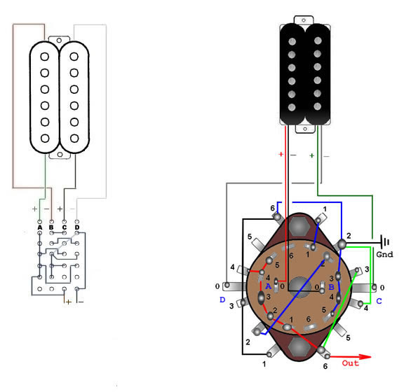
- Real-Life Examples: Rotary switches with specific contact sequences are used in guitar pickup selectors, enabling different combinations of pickups to be engaged.
- Wiring Implications: The contact arrangement directly affects the wiring scheme of the switch, dictating the connections between terminals and contacts.
- Circuit Functionality: The sequence in which contacts connect shapes the electrical functionality of the switch, influencing the behavior of the circuits it controls.
In essence, understanding the Contact Arrangement is pivotal in selecting and wiring rotary switches effectively. It allows engineers to tailor the switch’s behavior to specific application requirements, ensuring reliable and efficient control of electrical circuits and functions.
Electrical Rating
Within the context of Rotary Switch Wiring Diagrams, the Electrical Rating, defined by current and voltage limits, plays a critical role in ensuring safe and reliable operation of the switch. It establishes the electrical boundaries within which the switch can function without compromising its integrity or posing safety hazards.
The current rating specifies the maximum amount of electrical current that can flow through the switch without causing excessive heating or damage to the contacts. Exceeding the current rating can lead to arcing, contact welding, and potential fire risks. Similarly, the voltage rating indicates the maximum voltage that the switch can withstand without experiencing electrical breakdown or insulation failure.
Incorporating the Electrical Rating into Rotary Switch Wiring Diagrams is paramount for several reasons. Firstly, it guides engineers in selecting switches that are appropriately sized for the intended application, preventing overloading and ensuring longevity. Secondly, it facilitates the proper selection of conductors and other electrical components, ensuring compatibility and minimizing the risk of damage due to excessive current or voltage.
Real-life examples of Electrical Ratings in Rotary Switch Wiring Diagrams can be found in industrial control systems, where switches are used to control high-power motors and machinery. The Electrical Rating ensures that the switch can handle the high currents and voltages associated with these applications, preventing catastrophic failures and maintaining a safe operating environment.
Understanding the connection between Electrical Rating and Rotary Switch Wiring Diagrams empowers engineers to design and implement electrical systems with confidence. It enables them to select and wire switches that meet the specific requirements of their applications, ensuring safety, reliability, and optimal performance.
Physical Dimensions
In the realm of Rotary Switch Wiring Diagrams, the Physical Dimensions, encompassing the size and shape of the switch, hold significant importance as they directly impact the wiring configuration and overall functionality of the switch. This connection stems from the fact that the Physical Dimensions influence the arrangement of terminals, contacts, and other internal components within the switch.
The size of the switch, primarily its diameter and height, determines the number of terminals and contacts that can be accommodated. A larger switch allows for more terminals and contacts, enabling the control of a greater number of circuits or functions. Conversely, a smaller switch may have limited space for terminals and contacts, restricting its functionality.
Real-life examples of the Physical Dimensions influencing Rotary Switch Wiring Diagrams can be found in industrial control panels and audio mixing consoles. In industrial settings, larger rotary switches are often used to control complex machinery, requiring numerous circuits and functions. In contrast, smaller rotary switches are commonly found in audio mixers, where space is constrained and the control of a limited number of audio channels is required.
Understanding the connection between Physical Dimensions and Rotary Switch Wiring Diagrams is crucial for engineers and technicians involved in electrical system design and installation. It enables them to select switches that are appropriately sized for the intended application, ensuring adequate space for wiring and preventing overcrowding or interference with other components.
Mounting Type
In the context of Rotary Switch Wiring Diagrams, the Mounting Type, encompassing the method of securing the switch to a panel or surface, plays a crucial role in ensuring reliable operation and integration within electrical systems.
- Panel Mount: Switches designed to be mounted on a flat panel, utilizing screws or other fasteners to secure them. This mounting type provides a stable and robust connection, ideal for industrial control panels and equipment.
- Surface Mount: Switches intended to be mounted directly onto a surface, often using adhesive or bolts. This method offers flexibility in placement, making it suitable for applications where space is limited or panel mounting is not feasible.
- Threaded Mount: Switches equipped with a threaded body, allowing them to be screwed into a pre-tapped hole on a panel or surface. This mounting type provides a secure and vibration-resistant connection, often used in harsh environments or applications involving heavy machinery.
- Snap-In Mount: Switches designed to snap into a pre-cut hole on a panel or chassis. This method offers quick and tool-less installation, making it ideal for high-volume applications and consumer electronics.
Understanding the Mounting Type and its implications is essential for selecting the appropriate rotary switch and incorporating it effectively into the overall wiring diagram. By considering the panel or surface characteristics, space constraints, and environmental factors, engineers can ensure a secure and reliable installation, optimizing the switch’s performance and longevity.


Related Posts


