An Msd Hei Distributor Wiring Diagram is a schematic representation of the electrical connections and components within an automotive distributor utilizing the Magnetic Sensor (MS) High Energy Ignition (HEI) system. It maps out the flow of electrical current through the distributor, including the ignition coil, electronic control module, and sensor, providing a visual guide for troubleshooting, repair, and installation.
The Msd Hei Distributor Wiring Diagram holds significant importance as it simplifies the complex wiring configurations and ensures proper functionality of the ignition system. Its benefits include enhanced engine performance, improved fuel efficiency, and reduced emissions. Historically, the development of integrated electronic ignition systems like the HEI system revolutionized the automotive industry, replacing points and condenser-based distributors, leading to more efficient and reliable ignition.
This article will delve deeper into the specific components and connections illustrated in the Msd Hei Distributor Wiring Diagram, exploring its role in the ignition process, discussing troubleshooting techniques, and examining advancements in ignition technology.
The Msd Hei Distributor Wiring Diagram is a versatile tool with several key aspects that contribute to its significance and functionality within the automotive ignition system.
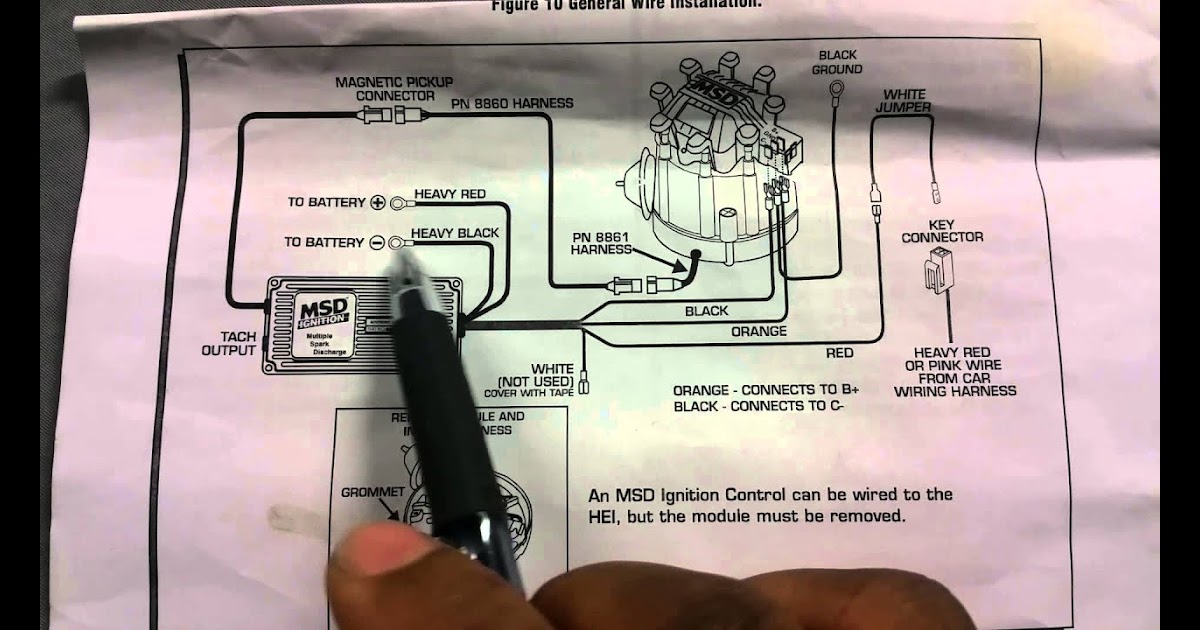
- Schematic Representation: The diagram illustrates the electrical connections and components within the distributor, providing a visual guide for understanding the flow of electrical current.
- Troubleshooting: It aids in diagnosing and resolving electrical issues within the distributor, simplifying the troubleshooting process.
- Repair and Installation: The diagram serves as a reference during repair and installation procedures, ensuring proper connections and component placement.
- Ignition Coil: The diagram specifies the wiring connections to the ignition coil, which generates the high voltage necessary for spark plugs.
- Electronic Control Module: It outlines the connections to the electronic control module, which manages the timing and duration of spark delivery.
- Sensor: The diagram shows the wiring to the sensor, which detects engine position and triggers the ignition.
- Engine Performance: A properly wired distributor, as guided by the diagram, contributes to optimal engine performance and efficiency.
- Fuel Efficiency: Precise ignition timing, facilitated by the diagram, enhances fuel economy by optimizing combustion.
- Reduced Emissions: Efficient ignition reduces unburned fuel and emissions, contributing to environmental protection.
These aspects highlight the importance of the Msd Hei Distributor Wiring Diagram in maintaining a well-functioning ignition system, ensuring reliable engine operation, improved performance, and environmental sustainability.
Schematic Representation
The schematic representation forms the foundation of the Msd Hei Distributor Wiring Diagram, providing a clear visual guide to the complex electrical connections and components within the distributor. It enables technicians and enthusiasts to comprehend the flow of electrical current, facilitating troubleshooting, repair, and installation.
Within the Msd Hei Distributor Wiring Diagram, the schematic representation plays a critical role in understanding the relationship between the ignition coil, electronic control module, sensor, and other components. By tracing the electrical connections illustrated in the diagram, individuals can identify potential issues, ensuring proper functionality of the distributor and ignition system as a whole.
Real-life applications of this understanding include diagnosing and resolving ignition problems, optimizing engine performance, and enhancing fuel efficiency. The schematic representation empowers individuals to make informed decisions regarding maintenance and repairs, potentially saving time and expenses.
In summary, the schematic representation within the Msd Hei Distributor Wiring Diagram is a crucial component for understanding the electrical connections and components of the distributor. It serves as a visual guide for troubleshooting, repair, and installation, contributing to optimal engine performance, fuel efficiency, and reduced emissions.
Troubleshooting
The Msd Hei Distributor Wiring Diagram plays a crucial role in troubleshooting electrical issues within the distributor, as it provides a visual representation of the electrical connections and components. By understanding the schematic layout, technicians can trace the flow of current and identify potential problems.
For instance, if an engine is experiencing ignition problems, the wiring diagram can guide the technician in checking the connections to the ignition coil, electronic control module, and sensor. By following the diagram, they can quickly identify loose or damaged wires, faulty components, or incorrect connections, simplifying the troubleshooting process.
The practical application of this understanding enables technicians to diagnose and resolve electrical issues efficiently, minimizing downtime and ensuring optimal engine performance. Moreover, the wiring diagram serves as a valuable reference during repairs, preventing incorrect connections and potential damage to the distributor or other components.
In summary, the troubleshooting aspect of the Msd Hei Distributor Wiring Diagram is a critical component for diagnosing and resolving electrical issues within the distributor. By providing a visual guide to the electrical connections and components, it simplifies the troubleshooting process, reduces downtime, and contributes to efficient engine operation.
Repair and Installation
The Msd Hei Distributor Wiring Diagram plays a crucial role in the repair and installation process, acting as a visual guide to ensure proper connections and component placement within the distributor. Technicians rely on the diagram to accurately reconnect wires, replace faulty components, and assemble the distributor correctly.
For instance, when replacing a worn-out ignition coil, the wiring diagram provides precise guidance on which wires to connect to the new coil, ensuring correct polarity and avoiding potential damage to the electrical system. Similarly, if the electronic control module needs to be replaced, the diagram specifies the pinouts and connections, preventing incorrect installation that could lead to ignition problems.
The practical implications of understanding the repair and installation aspect of the Msd Hei Distributor Wiring Diagram are significant. Accurate repairs and installations contribute to optimal engine performance, reliability, and longevity. Moreover, it reduces the risk of electrical faults, ignition problems, and potential damage to the distributor or other components.
In summary, the repair and installation aspect of the Msd Hei Distributor Wiring Diagram is a critical component for ensuring proper connections and component placement during maintenance and repairs. By following the diagram, technicians can confidently perform complex tasks, leading to reliable engine operation and extended distributor life.
Ignition Coil
Within the comprehensive framework of the Msd Hei Distributor Wiring Diagram, the ignition coil plays a pivotal role in the ignition process, and the diagram provides crucial information regarding its wiring connections. Understanding these connections is essential for ensuring proper ignition functionality and optimal engine performance.
- Wiring Specifications: The diagram outlines the specific wiring connections to the ignition coil, including the power supply, ground, and connections to the electronic control module and sensor. Accurate wiring is critical to ensure the coil receives the necessary voltage and signals to generate high-voltage sparks.
- Coil Resistance: The diagram may also specify the resistance specifications for the ignition coil. Proper coil resistance is essential for generating the correct voltage and current required for spark plug ignition.
- Coil Type: The diagram can help identify the type of ignition coil used in the distributor, such as an internal or external coil. This information is important for selecting the appropriate replacement coil and ensuring compatibility with the distributor.
- Troubleshooting: By understanding the wiring connections to the ignition coil, technicians can effectively troubleshoot ignition problems. For instance, if the engine is experiencing misfires or ignition issues, the diagram can guide them in checking the coil connections, ensuring proper continuity, and identifying any potential faults.
Overall, the ignition coil aspect of the Msd Hei Distributor Wiring Diagram provides valuable insights into the electrical connections and specifications necessary for the coil to generate the high voltage required for spark plugs. This information is crucial for maintaining a properly functioning ignition system, optimizing engine performance, and facilitating effective troubleshooting.
Electronic Control Module
Within the comprehensive framework of the Msd Hei Distributor Wiring Diagram, the electronic control module (ECM) serves as the central brain of the ignition system, managing the timing and duration of spark delivery. Understanding the wiring connections to the ECM is essential for ensuring optimal engine performance, fuel efficiency, and reduced emissions.
- ECM Pinouts: The diagram provides a detailed layout of the ECM pinouts, specifying the purpose and function of each pin. This information is crucial for proper installation, troubleshooting, and repair of the ECM and its connections.
- Sensor Inputs: The diagram outlines the wiring connections to various sensors, such as the crankshaft position sensor and camshaft position sensor. These sensors provide critical information to the ECM, enabling it to determine the engine’s position and speed, which are essential for precise spark timing.
- Ignition Coil Control: The diagram specifies the wiring connections to the ignition coil, detailing how the ECM controls the coil’s charging and discharging process. This information is vital for ensuring the generation of high-voltage sparks at the appropriate time.
- Dwell Time Adjustment: The diagram may also provide instructions on adjusting the dwell time, which refers to the duration of current flow through the ignition coil. Proper dwell time is crucial for generating strong sparks and optimizing ignition performance.
In summary, the electronic control module aspect of the Msd Hei Distributor Wiring Diagram provides comprehensive insights into the wiring connections and functionality of the ECM, enabling technicians and enthusiasts to maintain, troubleshoot, and optimize the ignition system for maximum engine performance and efficiency.
Sensor
Within the intricate network of the Msd Hei Distributor Wiring Diagram, the sensor plays a pivotal role in orchestrating the ignition process, making it a crucial component for optimal engine performance. The diagram provides a comprehensive overview of the wiring connections to the sensor, enabling technicians and enthusiasts to understand its function, troubleshoot issues, and ensure proper operation.
- Crankshaft Position Sensor: The diagram specifies the wiring connections to the crankshaft position sensor, which monitors the rotational speed and position of the crankshaft. This information is vital for the electronic control module (ECM) to determine the engine’s timing and synchronize the spark delivery accordingly.
- Camshaft Position Sensor: The diagram outlines the wiring connections to the camshaft position sensor, which detects the position of the camshaft. This information enables the ECM to control variable valve timing systems, optimizing engine performance and efficiency across different operating conditions.
- Knock Sensor: The diagram may also include wiring connections to a knock sensor, which detects engine knock or detonation. This information is used by the ECM to adjust ignition timing, preventing potential engine damage and optimizing performance.
- Troubleshooting: Understanding the wiring connections to the sensor is essential for troubleshooting ignition problems. By following the diagram, technicians can check sensor connections, measure sensor signals, and identify potential faults, ensuring accurate diagnosis and repair.
In summary, the sensor aspect of the Msd Hei Distributor Wiring Diagram provides valuable insights into the wiring connections and functionality of the sensor, enabling technicians and enthusiasts to maintain, troubleshoot, and optimize the ignition system for maximum engine performance, fuel efficiency, and reduced emissions.
Engine Performance
The intricate relationship between the Msd Hei Distributor Wiring Diagram and engine performance is rooted in the precise control it provides over the ignition process, directly influencing the efficiency and performance of the engine. A properly wired distributor, as guided by the diagram, ensures that the spark plugs receive the necessary electrical current at the optimal time, resulting in efficient combustion and maximum power output.
Real-life examples within the Msd Hei Distributor Wiring Diagram illustrate this connection. When the ignition timing is correctly set according to the diagram, the engine runs smoother, exhibits improved acceleration, and delivers optimal fuel economy. Conversely, incorrect wiring or faulty components within the distributor can lead to misfiring, engine knocking, and decreased performance.
The practical applications of this understanding empower technicians and enthusiasts to optimize engine performance through accurate wiring and maintenance of the distributor. By adhering to the specifications outlined in the diagram, they can ensure precise ignition timing, maximize combustion efficiency, and minimize engine wear and tear. This knowledge also enables troubleshooting and repair of ignition problems, restoring optimal engine operation.
In summary, the Msd Hei Distributor Wiring Diagram is a critical component for achieving optimal engine performance and efficiency. It provides a roadmap for proper wiring and maintenance, empowering individuals to harness the full potential of their engines.
Fuel Efficiency
Within the comprehensive framework of the Msd Hei Distributor Wiring Diagram, fuel efficiency emerges as a crucial aspect, directly influenced by the precise ignition timing it facilitates. By optimizing combustion, the diagram contributes to enhanced fuel economy, leading to cost savings and reduced environmental impact.
- Optimized Combustion Timing: The diagram ensures that spark plugs receive the electrical current at precisely the right moment, aligning with the optimal point in the engine’s combustion cycle. This precise timing promotes complete and efficient combustion, minimizing wasted fuel and maximizing power output.
- Reduced Engine Load: Precise ignition timing reduces the load on the engine, as it doesn’t have to work as hard to overcome inefficient combustion. This translates to improved fuel economy and reduced wear and tear on engine components.
- Real-Life Examples: Vehicles equipped with distributors wired according to the Msd Hei Distributor Wiring Diagram often exhibit noticeable improvements in fuel efficiency. By optimizing ignition timing, drivers can potentially increase their mileage and reduce their fuel consumption.
- Environmental Implications: Enhanced fuel efficiency directly translates to reduced emissions, as less fuel is burned for the same amount of power output. This contributes to cleaner air and a healthier environment.
In conclusion, the Msd Hei Distributor Wiring Diagram plays a significant role in improving fuel efficiency by facilitating precise ignition timing. By optimizing combustion, it reduces wasted fuel, decreases engine load, and minimizes emissions, contributing to both economic and environmental benefits.
Reduced Emissions
Within the context of the Msd Hei Distributor Wiring Diagram, reducing emissions emerges as a crucial aspect, directly influenced by the efficient ignition it facilitates. By minimizing unburned fuel and optimizing combustion, the diagram contributes to a cleaner environment and reduced ecological impact.
- Catalytic Converter Efficiency: Precise ignition timing ensures that the catalytic converter operates at its optimal efficiency. Reduced unburned fuel means fewer pollutants entering the converter, allowing it to effectively remove harmful emissions.
- Improved Fuel Economy: Efficient ignition leads to improved fuel economy, directly reducing the amount of fuel consumed. This reduction in fuel consumption translates to lower greenhouse gas emissions.
- Real-Life Examples: Vehicles equipped with distributors wired according to the Msd Hei Distributor Wiring Diagram often exhibit reduced emissions levels. By optimizing ignition timing, drivers can contribute to cleaner air and a healthier environment.
- Environmental Regulations: Stringent environmental regulations worldwide have made reducing emissions a top priority for vehicle manufacturers. The Msd Hei Distributor Wiring Diagram supports compliance with these regulations by facilitating efficient ignition and minimizing emissions.
In conclusion, the Msd Hei Distributor Wiring Diagram plays a significant role in reducing emissions by ensuring efficient ignition and minimizing unburned fuel. This not only contributes to environmental protection but also aligns with the growing demand for eco-friendly transportation solutions.


![[DIAGRAM] Only 4 Pin Gm Hei Distributor Wiring Diagram](https://i0.wp.com/www.manualsdir.com/manuals/256331/1/msd-8875-wiring-harness-gm-hei-installation-page1.png?w=665&ssl=1)


Related Posts


