Gooseneck Trailer Wiring Diagram is a specific electrical configuration that connects a gooseneck trailer to a towing vehicle. It outlines the placement and functions of various wires, ensuring proper communication between the two vehicles for crucial lighting, braking, and other electrical systems.
Proper trailer wiring is essential for safe and legal operation. It prevents electrical malfunctions, ensures optimal lighting for night-time visibility, and facilitates reliable braking for both the trailer and the towing vehicle. A notable historical development occurred in the 1960s with the standardization of trailer wiring, enhancing compatibility and safety.
This article will delve into the detailed components, functions, and best practices associated with gooseneck trailer wiring diagrams, providing valuable insights for both DIY enthusiasts and professional technicians.
The key aspects of a Gooseneck Trailer Wiring Diagram are crucial for understanding its functionality and ensuring a safe and reliable connection between the towing vehicle and the trailer.
- Circuit Protection: Fuses or circuit breakers safeguard against electrical overloads.
- Conductor Size: Wire thickness determines current-carrying capacity and voltage drop.
- Connector Types: Compatible connectors ensure secure and weather-resistant connections.
- Grounding: Proper grounding provides a safe path for electrical current.
- Lighting Functions: Wiring for running lights, brake lights, turn signals, and hazard lights.
- Braking Functions: Electric brakes require proper wiring for actuation and control.
- Auxiliary Functions: Wiring for additional features like backup cameras or refrigeration units.
- Color Coding: Standardized wire colors facilitate identification and troubleshooting.
- Trailer Identification: Wiring includes a unique trailer identification number.
These aspects work together to establish a functional electrical system for the trailer, ensuring proper lighting, braking, and communication with the towing vehicle. Understanding these key aspects is essential for proper installation, maintenance, and troubleshooting of gooseneck trailer wiring diagrams.
Circuit Protection
In the context of Gooseneck Trailer Wiring Diagrams, circuit protection is paramount to prevent electrical overloads and ensure the safety of both the towing vehicle and the trailer.
- Fuses: Small, expendable devices that break the circuit when excessive current flows, protecting against electrical fires.
- Circuit Breakers: Reusable switches that trip when current exceeds a safe threshold, allowing for reset after troubleshooting.
- Proper Sizing: Fuses and circuit breakers must be appropriately sized to handle the maximum current draw of the trailer’s electrical system.
- Placement: Circuit protection devices should be placed in accessible locations for easy maintenance and replacement.
By incorporating circuit protection into Gooseneck Trailer Wiring Diagrams, potential electrical hazards are minimized, ensuring a safer and more reliable towing experience.
Conductor Size
Within the framework of Gooseneck Trailer Wiring Diagrams, conductor size plays a critical role in ensuring the safe and efficient operation of electrical systems. The thickness of the wire used directly influences its ability to carry current and minimize voltage drop, which are essential considerations for reliable trailer lighting, braking, and other functions.
- Current-Carrying Capacity: The thickness of the wire determines the amount of electrical current it can safely conduct. Insufficient wire thickness can lead to overheating and potential fire hazards.
- Voltage Drop: As electrical current flows through a wire, some voltage is lost due to resistance. Thicker wires reduce resistance, minimizing voltage drop and ensuring that electrical devices receive adequate power.
- Wire Gauge: Wire thickness is typically measured using wire gauge, with lower gauge numbers indicating thicker wires. For gooseneck trailer wiring, 10-12 gauge wire is commonly used for high-current applications, while 14-16 gauge wire is suitable for lower-current circuits.
- Conductor Material: Copper is the most widely used conductor material due to its excellent electrical conductivity. Aluminum can also be used, but it requires larger wire sizes to achieve the same current-carrying capacity.
Understanding the relationship between conductor size and current-carrying capacity/voltage drop is crucial for designing and installing effective Gooseneck Trailer Wiring Diagrams. Proper wire selection ensures that electrical systems function reliably, preventing potential hazards and ensuring a safe and efficient towing experience.
Connector Types
Within the context of Gooseneck Trailer Wiring Diagrams, connector types are of paramount importance in ensuring the secure and weather-resistant connection of electrical components. These connectors serve as the physical interface between the trailer and the towing vehicle, carrying electrical signals and power to various systems.
The compatibility of connectors is a critical aspect of Gooseneck Trailer Wiring Diagrams. Incompatible connectors can lead to poor electrical connections, arcing, overheating, and potential fire hazards. Therefore, it is essential to use connectors that are specifically designed for the application and meet industry standards.
Real-life examples of connector types used in Gooseneck Trailer Wiring Diagrams include 7-pin and 12-pin connectors. These connectors are designed to withstand the harsh conditions of towing, including exposure to moisture, dirt, and vibration. They feature weather-resistant seals and locking mechanisms to ensure a secure connection and prevent corrosion.
Understanding the importance of compatible connectors in Gooseneck Trailer Wiring Diagrams has practical applications in ensuring the safety and reliability of trailer electrical systems. Proper connector selection and installation can prevent electrical malfunctions, reduce the risk of accidents, and extend the lifespan of the trailer’s electrical components.
Grounding
Within the context of Gooseneck Trailer Wiring Diagrams, grounding plays a crucial role in ensuring the safe and proper functioning of electrical systems. It provides a conductive path for electrical current to return to its source, preventing hazardous voltage buildup and potential electrical shocks.
- Chassis Grounding: The trailer’s chassis serves as the primary grounding point, connecting all electrical components to the towing vehicle’s frame.
- Dedicated Ground Wire: A dedicated ground wire, typically green or bare copper, runs from the trailer’s electrical panel to the chassis, providing a low-resistance path for current to flow.
- Grounding Points: Multiple grounding points throughout the trailer’s electrical system ensure redundancy and reduce the risk of ground loops, which can cause interference and electrical malfunctions.
- Safety Implications: Proper grounding prevents stray electrical current from flowing through unintended paths, reducing the risk of electrical fires, shocks, and other hazards.
Understanding the significance of grounding in Gooseneck Trailer Wiring Diagrams is essential for ensuring the safety and reliability of trailer electrical systems. Proper grounding practices minimize the potential for electrical hazards, safeguarding both the trailer and its occupants.
Lighting Functions
Within the context of Gooseneck Trailer Wiring Diagrams, lighting functions play a crucial role in ensuring the safety and visibility of both the trailer and the towing vehicle. Proper wiring is essential for these lighting systems to function correctly, enabling clear communication with other vehicles on the road.
-
Running Lights:
Running lights provide visibility to the trailer when it is parked or at night. They are typically wired to the trailer’s clearance lights and side marker lights.
-
Brake Lights:
Brake lights indicate to following vehicles that the trailer is slowing down or stopping. They are wired to the trailer’s brake pedal and typically consist of red lights mounted on the rear of the trailer.
-
Turn Signals:
Turn signals communicate the trailer’s intended direction of travel. They are wired to the trailer’s turn signal switch and typically involve amber lights mounted on the sides of the trailer.
-
Hazard Lights:
Hazard lights are used to indicate a hazard or emergency situation. They are wired to a separate switch and typically involve flashing amber lights mounted on all four corners of the trailer.
These lighting functions are essential for safe towing and must be properly wired according to the Gooseneck Trailer Wiring Diagram. Incorrect wiring can lead to non-functioning lights, which can compromise safety and increase the risk of accidents.
Braking Functions
Within the context of Gooseneck Trailer Wiring Diagrams, braking functions assume paramount importance for the safe operation of both the trailer and the towing vehicle. Electric brakes, widely used in gooseneck trailers, rely on proper wiring for their effective actuation and control, ensuring timely and reliable braking response.
-
Brake Controller:
The brake controller, mounted in the towing vehicle, serves as the central component for actuating the trailer’s electric brakes. It receives input from the driver’s brake pedal and modulates the electrical signal sent to the trailer’s brakes.
-
Wiring Harness:
The wiring harness, typically a 4-wire system, carries electrical signals and power between the brake controller and the trailer’s brakes. Proper installation of the harness is critical to ensure a strong electrical connection and prevent malfunctions.
-
Brake Magnets:
Brake magnets, mounted on the trailer’s axles, convert electrical energy into mechanical force to engage the trailer’s brakes. Correct wiring is essential for delivering the necessary current to the magnets, ensuring adequate braking power.
-
Grounding:
Proper grounding of the trailer’s electrical system is crucial for effective brake operation. A dedicated ground wire provides a low-resistance path for electrical current to return to its source, preventing voltage fluctuations and ensuring reliable braking.
Understanding the importance of proper wiring for braking functions in Gooseneck Trailer Wiring Diagrams is essential for ensuring the safety and control of trailer operations. Correctly installed and maintained wiring guarantees timely and effective braking, reducing the risk of accidents and enhancing overall towing safety.
Auxiliary Functions
Within the comprehensive framework of Gooseneck Trailer Wiring Diagrams, auxiliary functions play a vital role in enhancing the utility and functionality of trailers. These functions involve wiring for additional features that extend beyond the basic lighting and braking systems, enabling the integration of various amenities and accessories.
-
Backup Cameras:
Backup cameras provide an expanded field of vision for the driver, enhancing safety and maneuverability when reversing the trailer. Their wiring involves connecting a camera mounted on the rear of the trailer to a display monitor in the towing vehicle.
-
Refrigeration Units:
Refrigeration units are essential for temperature-controlled transportation of perishable goods. Their wiring involves connecting the refrigeration unit to the trailer’s electrical system, ensuring a reliable power supply for maintaining the desired temperature.
-
Auxiliary Lighting:
Auxiliary lighting systems, such as work lights or LED strips, enhance visibility and safety in low-light conditions. Their wiring involves connecting the lighting fixtures to the trailer’s electrical system, providing additional illumination for specific areas.
-
Battery Chargers:
Battery chargers maintain the charge of auxiliary batteries used to power various accessories or provide backup power. Their wiring involves connecting the charger to the trailer’s electrical system and the auxiliary battery.
These auxiliary functions, when properly integrated into Gooseneck Trailer Wiring Diagrams, greatly enhance the functionality and convenience of trailers. They enable drivers to safely navigate and operate trailers, transport temperature-sensitive goods, and utilize additional amenities, contributing to an overall improved towing experience.
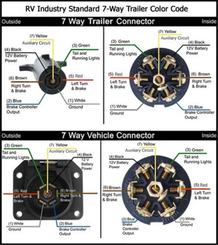
Color Coding
Within the realm of Gooseneck Trailer Wiring Diagrams, color coding of wires plays a pivotal role in simplifying the identification and troubleshooting of electrical connections. By adhering to standardized color codes, electricians and technicians can quickly discern the function of each wire, enabling efficient and precise troubleshooting.
Color coding serves as a critical component of Gooseneck Trailer Wiring Diagrams, as it provides a universal language for electrical connections. This standardization eliminates confusion and reduces the risk of mismatched or incorrectly wired connections, which could lead to electrical malfunctions or safety hazards. Each wire is assigned a specific color based on its intended purpose, such as ground, power, or lighting, making it easy to trace and identify even in complex wiring systems.
Real-life examples of color coding in Gooseneck Trailer Wiring Diagrams include:
- Black wires typically indicate ground connections.
- Red wires are commonly used for brake lights.
- Yellow wires are often associated with turn signals.
- Blue wires may be used for auxiliary lighting.
By following these standardized color codes, technicians can quickly identify and troubleshoot any electrical issues, ensuring proper functioning of the trailer’s lighting, braking, and other electrical systems.
Understanding the significance of color coding in Gooseneck Trailer Wiring Diagrams has practical applications in both troubleshooting and maintenance. It enables technicians to swiftly diagnose and repair electrical faults, reducing downtime and enhancing overall safety. Furthermore, color coding facilitates the addition or modification of electrical components, as new wires can be easily integrated into the existing wiring system by following the standardized color scheme.
Trailer Identification
Within the intricate network of Gooseneck Trailer Wiring Diagrams, the inclusion of a unique trailer identification number holds significant value. This unique identifier serves as a crucial component, deeply intertwined with the overall functionality and safety of the trailer’s electrical system.
The trailer identification number, often displayed prominently on the trailer’s exterior, plays a pivotal role in facilitating communication between the trailer and the towing vehicle. It acts as an electronic fingerprint, enabling various systems to recognize and interact with the trailer seamlessly. This identification number is embedded within the trailer’s wiring diagram, ensuring its accessibility to all electrical components.
Real-life examples underscore the practical applications of trailer identification numbers. During inspections or troubleshooting, technicians can quickly identify the specific trailer and access its detailed wiring diagram based on its unique identification number. This streamlined process enhances efficiency and accuracy in resolving electrical issues, minimizing downtime and ensuring the trailer’s safe operation.
Understanding the connection between trailer identification and Gooseneck Trailer Wiring Diagrams is essential for both professional technicians and trailer owners. It empowers them to effectively maintain, troubleshoot, and modify the trailer’s electrical system with confidence. This understanding promotes safety, reliability, and optimal performance of the trailer, contributing to a seamless and successful towing experience.


Related Posts


