A “1999 Dodge Ram 1500 Radio Wiring Diagram” is a schematic representation of the electrical connections and components within the radio system of a 1999 Dodge Ram 1500 pickup truck. This diagram provides detailed instructions for the installation, repair, and troubleshooting of the radio system.
Such wiring diagrams are crucial for technicians, enthusiasts, and individuals performing electrical work on their vehicles. They ensure accurate and efficient installation, prevent electrical hazards, and enhance the performance and functionality of the radio system. A significant historical development in automotive electrical systems was the standardization of color coding for wires, which greatly simplified wiring diagrams and made them more user-friendly.
This article delves into the intricacies of the 1999 Dodge Ram 1500 Radio Wiring Diagram, providing an in-depth examination of its components, connections, and troubleshooting techniques. It is an indispensable resource for anyone seeking a comprehensive understanding of this electrical system.
The 1999 Dodge Ram 1500 Radio Wiring Diagram, as a comprehensive guide to the electrical connections and components within the radio system, encompasses several essential aspects that are crucial for understanding its functionality and enabling effective troubleshooting and repairs.
- Components: Radio, amplifier, speakers, wiring harness
- Connections: Power, ground, signal, antenna
- Installation: Step-by-step instructions for proper radio installation
- Repair: Diagnostic and repair procedures for common radio issues
- Troubleshooting: Techniques for identifying and resolving electrical problems
- Color Coding: Standardized wire colors for ease of identification
- Safety Precautions: Guidelines for handling electrical components safely
- Tools and Materials: Essential tools and materials required for working with the radio system
- Testing Procedures: Methods for testing radio components and connections
- System Integration: Information on how the radio system interacts with other vehicle systems
These aspects provide a comprehensive framework for understanding and working with the 1999 Dodge Ram 1500 Radio Wiring Diagram. By comprehending the components, connections, and troubleshooting techniques, technicians, enthusiasts, and vehicle owners can ensure the proper installation, repair, and maintenance of the radio system, enhancing its performance and functionality.
Components
Delving into the components of a 1999 Dodge Ram 1500 Radio Wiring Diagram reveals the essential building blocks of the vehicle’s audio system. Understanding these components and their interconnections is crucial for effective troubleshooting, repairs, and upgrades.
- Radio: The heart of the audio system, responsible for receiving and processing radio signals, as well as controlling playback from other sources like CDs or MP3 players.
- Amplifier: Boosts the audio signal from the radio to provide sufficient power for driving the speakers. This component is not always present in all vehicles, but it enhances sound quality and volume.
- Speakers: Transducers that convert electrical signals into sound waves, producing the audio output we hear. The number and placement of speakers affect the sound quality and listening experience.
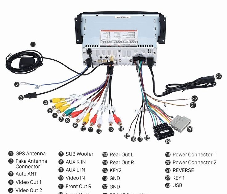
- Wiring Harness: A bundle of wires that connects all the components together, providing power, signal transmission, and control. Color-coded wires simplify identification and ensure proper connections.
These components work in harmony to deliver an enjoyable audio experience. By understanding their roles and interconnections, one can diagnose and resolve issues, optimize sound quality, and even upgrade the system with additional components or features.
Connections
In the realm of the 1999 Dodge Ram 1500 Radio Wiring Diagram, the connections for power, ground, signal, and antenna play a pivotal role in ensuring the proper functioning of the audio system. These connections establish the electrical pathways that allow the radio to receive signals, process audio, and deliver sound through the speakers. Understanding their relationship is crucial for troubleshooting, repairs, and modifications.
The power connection provides the necessary voltage to operate the radio and its components. The ground connection establishes a reference point for the electrical circuit, ensuring proper signal flow and preventing electrical noise. The signal connection carries the audio signals from the radio to the amplifier and speakers. Finally, the antenna connection enables the radio to receive radio signals from broadcast towers.
Real-life examples within the 1999 Dodge Ram 1500 Radio Wiring Diagram illustrate the practical significance of these connections. For instance, a loose power connection can cause the radio to malfunction or lose power intermittently. A faulty ground connection can introduce noise into the audio signal, resulting in static or crackling sounds. A damaged signal connection can disrupt the audio output, causing intermittent sound loss or distortion. Understanding these connections empowers individuals to identify and resolve common issues, ensuring optimal audio performance.
In summary, the connections for power, ground, signal, and antenna form the backbone of the 1999 Dodge Ram 1500 Radio Wiring Diagram. These connections enable the radio to operate effectively, and their proper understanding is essential for maintaining a reliable and enjoyable audio experience. By comprehending the cause and effect relationships between these connections and the radio’s functionality, individuals can diagnose and resolve issues, optimize sound quality, and even upgrade the system with additional components or features.
Installation
Within the comprehensive framework of the “1999 Dodge Ram 1500 Radio Wiring Diagram,” the aspect of “Installation: Step-by-step instructions for proper radio installation” holds great significance. It provides a structured and detailed guide for technicians, enthusiasts, and do-it-yourselfers to undertake the task of installing a radio system accurately and efficiently.
- Compatibility Assessment: Before embarking on the installation process, it is crucial to ensure compatibility between the chosen radio and the vehicle’s electrical system. This involves verifying the voltage requirements, physical dimensions, and any specific interface or adapter needs.
- Wiring Preparation: The wiring harness plays a vital role in connecting the radio to the vehicle’s electrical system. Proper preparation involves identifying the correct wires for power, ground, signal, and antenna connections, as well as ensuring secure and insulated connections.
- Mounting and Placement: Selecting an appropriate mounting location for the radio is essential for both functionality and aesthetics. The instructions typically provide specific dimensions and guidelines for creating the necessary mounting brackets or utilizing existing ones.
- Testing and Troubleshooting: Once the installation is complete, thorough testing is necessary to verify proper functionality. This involves powering on the system, checking for audio output, and addressing any potential issues that may arise.
These facets collectively emphasize the importance of meticulous planning, careful execution, and thorough testing during the radio installation process. By adhering to the step-by-step instructions provided in the “1999 Dodge Ram 1500 Radio Wiring Diagram,” individuals can ensure a successful installation, minimizing the risk of electrical hazards, performance issues, or damage to the vehicle’s electrical system.
Repair
Within the comprehensive “1999 Dodge Ram 1500 Radio Wiring Diagram,” the aspect of “Repair: Diagnostic and repair procedures for common radio issues” holds immense significance, offering invaluable guidance for troubleshooting and resolving radio-related problems. Understanding these procedures empowers individuals to identify the root causes of radio malfunctions and implement effective solutions.
- Identifying Electrical Faults: Electrical faults, such as loose connections or damaged wires, can disrupt the proper functioning of the radio system. The wiring diagram provides a visual representation of the electrical connections, aiding in the identification and repair of these faults.
- Troubleshooting Audio Output Issues: Audio output issues, such as no sound, distorted sound, or intermittent sound loss, can be caused by faulty speakers, amplifiers, or damaged wiring. The diagram helps isolate the affected component, enabling targeted troubleshooting and repairs.
- Addressing Radio Display Problems: Radio display problems, such as a blank screen or incorrect information, can indicate issues with the radio’s display unit or its connection to the main system. The wiring diagram provides insights into the display circuitry, facilitating the diagnosis and repair of these problems.
- Resolving Signal Reception Issues: Signal reception issues, such as weak or intermittent radio signals, can be caused by problems with the antenna or its connection. The diagram illustrates the antenna wiring and connections, allowing for proper troubleshooting and repairs to restore optimal signal reception.
These facets collectively highlight the importance of “Repair: Diagnostic and repair procedures for common radio issues” in the context of “1999 Dodge Ram 1500 Radio Wiring Diagram.” By providing a visual representation of the electrical connections and components, the diagram empowers individuals to systematically diagnose and repair radio-related problems, ensuring a reliable and enjoyable audio experience.
Troubleshooting
Within the comprehensive “1999 Dodge Ram 1500 Radio Wiring Diagram,” the aspect of “Troubleshooting: Techniques for identifying and resolving electrical problems” holds paramount importance, providing a systematic approach to diagnosing and rectifying electrical faults within the radio system. Understanding these techniques empowers individuals to pinpoint the root causes of electrical problems, implement effective solutions, and ensure optimal performance of the radio system.
- Identifying Faulty Components: Electrical problems can stem from faulty components, such as loose connections, damaged wires, or malfunctioning transistors. The diagram provides a visual representation of the electrical connections and components, enabling targeted testing and identification of the problematic component.
- Analyzing Circuit Behavior: Troubleshooting electrical problems involves analyzing the behavior of electrical circuits. The diagram provides insights into the signal flow, voltage levels, and current paths, allowing individuals to identify anomalies and trace the source of the problem.
- Interpreting Diagnostic Codes: Modern radios often incorporate self-diagnostic features that generate error codes. The diagram provides information on interpreting these codes, enabling individuals to quickly identify the nature of the problem and take appropriate action.
- Utilizing Specialized Tools: Advanced troubleshooting may require the use of specialized tools, such as multimeters and oscilloscopes. The diagram provides guidance on how to use these tools effectively to measure electrical parameters, such as voltage, resistance, and frequency, and isolate the source of the problem.
These facets collectively highlight the importance of “Troubleshooting: Techniques for identifying and resolving electrical problems” in the context of “1999 Dodge Ram 1500 Radio Wiring Diagram.” By providing a visual representation of the electrical connections and components, the diagram empowers individuals to systematically diagnose and repair electrical problems, ensuring a reliable and enjoyable audio experience.
Color Coding
The aspect of “Color Coding: Standardized wire colors for ease of identification” plays a crucial role in the “1999 Dodge Ram 1500 Radio Wiring Diagram,” providing a systematic approach to wire identification, simplifying installation, repair, and troubleshooting procedures.
- Universal Standard: The color coding follows industry-wide standards, ensuring consistency across different vehicles and manufacturers, facilitating troubleshooting and repairs by both professional technicians and DIY enthusiasts.
- Simplified Wiring: Color-coded wires reduce the complexity of wiring harnesses, making it easier to trace connections, identify individual wires, and avoid mistakes during installation or repairs.
- Enhanced Safety: Standardized color coding promotes electrical safety by preventing accidental contact with live wires, reducing the risk of short circuits and electrical hazards.
- Time-Saving: The ease of wire identification provided by color coding significantly reduces the time required for installation, repairs, and troubleshooting, enhancing efficiency and productivity.
In summary, “Color Coding: Standardized wire colors for ease of identification” is an integral aspect of the “1999 Dodge Ram 1500 Radio Wiring Diagram,” ensuring efficient and accurate wiring practices. It simplifies identification, reduces errors, enhances safety, and saves time, making it a valuable tool for professionals and DIY enthusiasts alike.
Safety Precautions
In the context of the “1999 Dodge Ram 1500 Radio Wiring Diagram,” the aspect of “Safety Precautions: Guidelines for handling electrical components safely” holds paramount importance, establishing a framework for minimizing electrical hazards and ensuring personal safety during installation, repair, and troubleshooting procedures.
Electrical components, if mishandled, can pose significant risks, including electric shock, fires, and damage to the vehicle’s electrical system. The “1999 Dodge Ram 1500 Radio Wiring Diagram,” therefore, incorporates detailed safety guidelines that provide step-by-step instructions for safe handling of electrical components, ensuring the well-being of individuals undertaking these tasks.
Real-life examples of safety precautions within the “1999 Dodge Ram 1500 Radio Wiring Diagram” include:
- Disconnecting the vehicle’s battery before commencing any electrical work to eliminate the risk of electric shock.
- Using insulated tools and wearing appropriate safety gear, such as gloves and safety glasses, to prevent accidental contact with live wires.
- Following proper grounding procedures to ensure that electrical currents are safely discharged.
- Avoiding contact with sharp edges or exposed wires to prevent cuts or injuries.
Understanding and adhering to these safety precautions is critical for ensuring a safe and successful installation, repair, or troubleshooting experience. By emphasizing the importance of safety and providing clear guidelines, the “1999 Dodge Ram 1500 Radio Wiring Diagram” empowers individuals to confidently undertake electrical work on their vehicles, minimizing risks and ensuring their well-being.
Tools and Materials
Within the realm of the “1999 Dodge Ram 1500 Radio Wiring Diagram,” the aspect of “Tools and Materials: Essential tools and materials required for working with the radio system” holds critical significance. Understanding the cause-and-effect relationship between the two is paramount for effective installation, repair, and troubleshooting procedures.
The “1999 Dodge Ram 1500 Radio Wiring Diagram” serves as a comprehensive guide to the electrical connections and components within the radio system. However, to fully utilize this diagram and perform any practical work, a specific set of tools and materials is indispensable.
Real-life examples of essential tools and materials include screwdrivers, pliers, wire cutters, electrical tape, and a multimeter. These tools are necessary for tasks such as removing and installing the radio, connecting and disconnecting wires, and testing electrical circuits. Without the appropriate tools and materials, individuals may encounter difficulties or even safety hazards while working on the radio system.
The practical applications of understanding the connection between “Tools and Materials: Essential tools and materials required for working with the radio system” and “1999 Dodge Ram 1500 Radio Wiring Diagram” extend beyond basic installation and repairs. It empowers individuals to confidently diagnose and resolve electrical issues, modify or upgrade the radio system, and maintain optimal performance over time.
In summary, the “Tools and Materials: Essential tools and materials required for working with the radio system” are a critical component of the “1999 Dodge Ram 1500 Radio Wiring Diagram.” Understanding this relationship ensures that individuals have the necessary resources to effectively and safely handle electrical work on their vehicles.
Testing Procedures
Within the comprehensive framework of the “1999 Dodge Ram 1500 Radio Wiring Diagram,” “Testing Procedures: Methods for testing radio components and connections” holds significant importance, providing a structured approach to evaluating the functionality and integrity of the radio system. This aspect empowers individuals to pinpoint potential issues, ensure proper operation, and maintain optimal performance over time.
- Component Testing: Involves testing individual radio components, such as speakers, amplifiers, and the radio unit itself, to identify any faults or performance degradation.
- Circuit Continuity Testing: Utilizes a multimeter to check for complete electrical pathways between different points in the wiring harness, ensuring proper signal and power flow.
- Signal Tracing: Employs specialized tools to follow and analyze audio signals as they pass through the radio system, identifying any distortions or interruptions.
- Antenna Performance Testing: Assesses the functionality and signal reception capabilities of the antenna, ensuring optimal radio performance.
Understanding and applying these testing procedures enables individuals to diagnose and resolve a wide range of radio issues, from minor glitches to complex malfunctions. By systematically testing components and connections, they can identify the root cause of problems, implement targeted repairs, and restore the radio system to its intended functionality. These testing procedures are an indispensable part of the “1999 Dodge Ram 1500 Radio Wiring Diagram,” empowering individuals to maintain a reliable and enjoyable audio experience.
System Integration
Within the intricate framework of the “1999 Dodge Ram 1500 Radio Wiring Diagram,” the aspect of “System Integration: Information on how the radio system interacts with other vehicle systems” holds significant relevance, shedding light on the interconnected nature of various vehicle components and their influence on the radio system’s functionality.
- Navigation System Integration: The radio system may interface with a navigation system, enabling audio guidance and displaying route information on the radio’s screen.
- Steering Wheel Controls: Multifunction steering wheels often incorporate controls for the radio, allowing drivers to adjust volume, change stations, or answer calls without taking their hands off the wheel.
- Vehicle Information Display: Some vehicles display radio information, such as station presets or song titles, on the instrument cluster or a dedicated display screen.
- HVAC System Integration: Advanced climate control systems may allow users to control the audio system’s fan speed or temperature through voice commands or dedicated buttons.
Understanding “System Integration: Information on how the radio system interacts with other vehicle systems” empowers individuals to harness the full potential of their radio system, enhance their driving experience, and appreciate the intricate interplay between different vehicle components. This aspect of the “1999 Dodge Ram 1500 Radio Wiring Diagram” serves as a valuable resource for comprehending the interconnectedness of modern automotive systems.


Related Posts


