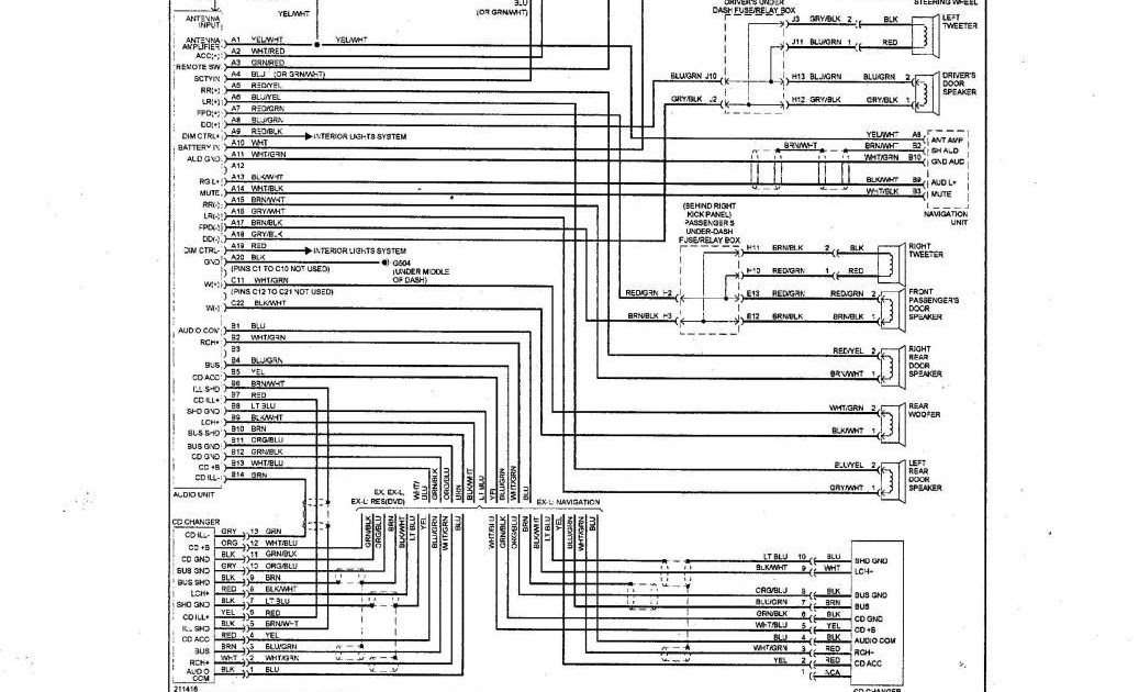
A 2008 Honda Civic Radio Wiring Diagram is a detailed schematic representation of the electrical connections and circuitry associated with the radio system in a 2008 Honda Civic vehicle.
It serves as a vital guide for automotive technicians, car audio enthusiasts, and anyone performing maintenance or troubleshooting on the vehicle’s radio components. This wiring diagram provides comprehensive information about wire colors, terminal locations, and signal paths, enabling users to correctly identify, connect, and diagnose issues within the radio system.
Understanding the 2008 Honda Civic Radio Wiring Diagram is crucial to ensure proper functionality, prevent electrical hazards, and facilitate seamless integration of aftermarket audio equipment. Its relevance extends to maintaining the vehicle’s entertainment system and ensuring safe and reliable operation.
Delving into the essential aspects of the “2008 Honda Civic Radio Wiring Diagram” is crucial for comprehending its significance and functionality within the vehicle’s audio system. The following key aspects provide a comprehensive overview:
- Accuracy: The diagram ensures precise representation of the electrical connections, ensuring reliable guidance during installation, troubleshooting, and maintenance.
- Comprehensiveness: It provides a complete overview of the radio system’s wiring, including wire colors, terminal locations, and signal paths.
- Color Coding: Standardized color coding facilitates easy identification of wires, simplifying the tracing process.
- Connector Types: Detailed illustrations of connector types guide users in selecting the appropriate connectors for secure connections.
- Grounding Points: Clear indication of grounding points ensures proper grounding of the radio system, preventing electrical malfunctions.
- Signal Paths: The diagram outlines the signal flow between different components, aiding in diagnosing signal issues.
- Power Supply: It specifies the power supply requirements and connections, ensuring compatibility with the vehicle’s electrical system.
- Antenna Connection: The diagram provides guidance on connecting the antenna to the radio system, optimizing signal reception.
- Speaker Connections: It outlines the connections between the radio and speakers, ensuring proper sound output and balance.
Understanding these aspects empowers automotive technicians, car audio enthusiasts, and vehicle owners with the knowledge to maintain, troubleshoot, and upgrade their Honda Civic’s radio system effectively, ensuring optimal performance and a seamless audio experience.
Accuracy: The diagram ensures precise representation of the electrical connections, ensuring reliable guidance during installation, troubleshooting, and maintenance.
Within the context of the “2008 Honda Civic Radio Wiring Diagram,” accuracy plays a pivotal role in providing reliable guidance during various tasks related to the vehicle’s radio system. Its precise representation of electrical connections empowers users to confidently perform installation, troubleshooting, and maintenance procedures, ensuring the optimal functioning of the audio system.
- Accurate Component Identification: The diagram accurately depicts the specific components within the radio system, including connectors, wires, and terminals. This detailed representation enables users to correctly identify and locate components, facilitating efficient troubleshooting and precise connections.
- Standardized Color Coding: The diagram adheres to standardized color coding conventions, ensuring consistency in wire identification. This universal color scheme allows users to easily trace wires throughout the system, simplifying the process of connecting and diagnosing issues.
- Verified Signal Paths: The diagram provides a verified representation of signal paths within the radio system. This information is crucial for diagnosing signal-related issues, as it allows users to trace the flow of signals and identify potential points of failure.
- Comprehensive Connector Details: The diagram includes comprehensive details about connectors, including their types, pinouts, and locations. This information is essential for selecting the appropriate connectors and ensuring secure connections, preventing electrical malfunctions and ensuring reliable performance.
In conclusion, the accuracy of the “2008 Honda Civic Radio Wiring Diagram” serves as a cornerstone for successful radio system maintenance and troubleshooting. Its precise representation of electrical connections, standardized color coding, verified signal paths, and comprehensive connector details empower users with the knowledge and guidance necessary to perform tasks efficiently and effectively, ensuring the optimal functioning of the audio system.
Comprehensiveness: It provides a complete overview of the radio system’s wiring, including wire colors, terminal locations, and signal paths.
The comprehensiveness of the “2008 Honda Civic Radio Wiring Diagram” manifests in its meticulous representation of the radio system’s wiring, encompassing wire colors, terminal locations, and signal paths. This exhaustive level of detail serves as the cornerstone for accurate and efficient maintenance, troubleshooting, and modification of the audio system.
Consider the following scenarios that underscore the practical applications of the diagram’s comprehensiveness:
- Precise Component Identification: When a malfunction occurs within the radio system, the comprehensive diagram enables technicians to pinpoint the affected component swiftly and accurately. By tracing wire colors and identifying terminal locations, they can isolate the issue and implement targeted repairs.
- Simplified Troubleshooting: The diagram’s detailed representation of signal paths empowers users to trace the flow of signals throughout the system. This facilitates the identification of signal disruptions or weak connections, enabling effective troubleshooting and rectification of audio issues.
- Seamless System Upgrades: For car audio enthusiasts seeking to enhance their sound system, the comprehensive diagram provides a clear roadmap for integrating aftermarket components. By understanding wire colors and terminal locations, they can confidently connect additional speakers, amplifiers, or subwoofers, ensuring seamless integration and optimal performance.
In essence, the comprehensiveness of the “2008 Honda Civic Radio Wiring Diagram” empowers users with a profound understanding of the radio system’s intricacies. This knowledge enables them to perform maintenance, troubleshooting, and upgrades with precision, ensuring the reliable performance and exceptional audio experience that the Honda Civic is renowned for.
Color Coding: Standardized color coding facilitates easy identification of wires, simplifying the tracing process.
Within the context of the “2008 Honda Civic Radio Wiring Diagram,” standardized color coding plays a pivotal role in simplifying the identification and tracing of wires, which is crucial for efficient maintenance, troubleshooting, and modification of the audio system. The consistent use of color-coded wires throughout the diagram and the corresponding wiring harness of the vehicle enables users to quickly and accurately locate specific wires, reducing the time and effort required for electrical work.
Consider the following real-life examples that demonstrate the practical significance of color coding within the “2008 Honda Civic Radio Wiring Diagram”:
- Rapid Fault Diagnosis: When troubleshooting electrical issues, technicians can swiftly identify the affected wire by its color code, allowing them to isolate the problem area and implement targeted repairs.
- Simplified Harness Assembly: During the assembly of aftermarket wiring harnesses, color coding ensures that wires are correctly connected to the appropriate terminals, reducing the risk of electrical malfunctions and ensuring reliable performance.
- Seamless Integration: When integrating additional audio components, such as amplifiers or subwoofers, the color coding in the diagram guides users in connecting wires to the correct terminals, ensuring compatibility and optimal sound output.
In summary, the standardized color coding employed in the “2008 Honda Civic Radio Wiring Diagram” serves as a critical component, enabling users to easily identify and trace wires. This understanding empowers them to perform electrical tasks with precision, efficiency, and confidence, contributing to the overall reliability and performance of the vehicle’s audio system.
Connector Types: Detailed illustrations of connector types guide users in selecting the appropriate connectors for secure connections.
Within the context of the “2008 Honda Civic Radio Wiring Diagram,” the inclusion of detailed illustrations of connector types plays a crucial role in ensuring secure connections throughout the audio system. These illustrations serve as a visual guide, assisting users in selecting the appropriate connectors for each electrical connection, thereby preventing malfunctions and ensuring the reliable operation of the radio system.
Consider the following real-life examples that underscore the importance of understanding connector types within the “2008 Honda Civic Radio Wiring Diagram”:
- Preventing Electrical Faults: By matching the correct connector types to their corresponding terminals, users can avoid electrical faults caused by loose or incompatible connections. This reduces the risk of damage to the radio system and other electrical components.
- Ensuring Signal Integrity: Secure connections provided by the appropriate connector types ensure the uninterrupted transmission of audio signals throughout the system. This contributes to the overall sound quality and prevents signal dropouts or distortions.
- Simplified Installation: Detailed illustrations of connector types guide users in selecting the right connectors for aftermarket audio components, simplifying the installation process and reducing the likelihood of errors.
In summary, the provision of detailed illustrations of connector types within the “2008 Honda Civic Radio Wiring Diagram” empowers users to make informed decisions when selecting connectors. This understanding contributes to the secure and reliable operation of the radio system, ensuring optimal audio performance and preventing electrical issues. By providing clear visual guidance, the diagram empowers users to approach electrical tasks with confidence and precision.
Grounding Points: Clear indication of grounding points ensures proper grounding of the radio system, preventing electrical malfunctions.
Within the context of the “2008 Honda Civic Radio Wiring Diagram,” the clear indication of grounding points plays a crucial role in establishing and maintaining a proper grounding system for the radio system. Grounding points serve as the electrical reference point for the system, ensuring that electrical currents flow safely and efficiently, preventing electrical malfunctions and ensuring reliable operation.
- Chassis Ground: The chassis ground connects the radio system to the metal frame of the vehicle, providing a low-resistance path for electrical current to flow. This prevents voltage spikes and ensures stable operation of the radio system.
- Battery Ground: The battery ground connects the radio system directly to the negative terminal of the vehicle’s battery. This provides a solid grounding reference for the system, minimizing electrical noise and interference.
- Antenna Ground: The antenna ground connects the radio system to the vehicle’s antenna. Proper grounding of the antenna ensures efficient signal reception and minimizes interference, resulting in improved radio performance.
- Component Grounds: In addition to the main grounding points, the wiring diagram also indicates grounding points for individual components within the radio system, such as speakers and amplifiers. These grounds ensure that each component is properly grounded, preventing electrical noise and ensuring optimal performance.
By providing clear indication of grounding points, the “2008 Honda Civic Radio Wiring Diagram” empowers users to ensure proper grounding of the radio system, preventing electrical malfunctions and ensuring reliable operation. Whether troubleshooting electrical issues, installing aftermarket components, or performing routine maintenance, the accurate representation of grounding points in the diagram serves as a valuable guide, contributing to the overall performance and longevity of the vehicle’s audio system.
Signal Paths: The diagram outlines the signal flow between different components, aiding in diagnosing signal issues.
Within the context of the “2008 Honda Civic Radio Wiring Diagram,” the precise representation of signal paths plays a critical role in facilitating the diagnosis and resolution of signal-related issues within the radio system. By outlining the flow of signals between different components, the diagram empowers users to identify points of failure and implement targeted repairs, ensuring optimal audio performance.
Consider the following real-life examples that underscore the practical significance of understanding signal paths within the “2008 Honda Civic Radio Wiring Diagram”:
- Troubleshooting Audio Dropouts: When experiencing intermittent audio dropouts, the diagram enables technicians to trace the signal path from the source (e.g., head unit) to the destination (e.g., speakers), identifying loose connections or faulty components along the way.
- Resolving Signal Interference: In cases of audio interference or noise, the diagram guides users in identifying potential sources of interference, such as faulty grounding or improper shielding, allowing them to implement appropriate mitigation strategies.
- Upgrading Audio Components: When upgrading audio components, such as speakers or amplifiers, the diagram provides a clear understanding of the signal flow, enabling users to integrate new components seamlessly and optimize system performance.
In summary, the detailed representation of signal paths within the “2008 Honda Civic Radio Wiring Diagram” serves as an invaluable tool for diagnosing and resolving signal-related issues. By providing a clear understanding of the signal flow, the diagram empowers users to approach troubleshooting and system upgrades with confidence and precision, ensuring the restoration and maintenance of optimal audio performance in the 2008 Honda Civic.
Power Supply: It specifies the power supply requirements and connections, ensuring compatibility with the vehicle’s electrical system.
The power supply aspect of the “2008 Honda Civic Radio Wiring Diagram” plays a crucial role in ensuring the seamless operation of the radio system by outlining the electrical requirements and connections necessary for its compatibility with the vehicle’s electrical system. This information is essential for both routine maintenance and troubleshooting, empowering users to identify and resolve issues related to power supply.
- Battery Connection: The diagram specifies the connection points to the vehicle’s battery, ensuring a reliable power source for the radio system. Proper battery connection is vital for maintaining stable voltage and preventing electrical malfunctions.
- Fuse Protection: The diagram indicates the location and amperage rating of fuses that protect the radio system from electrical overloads. Identifying and replacing blown fuses is crucial for restoring power and preventing damage to the radio components.
- Grounding: The diagram outlines the grounding points for the radio system, ensuring a proper electrical reference and minimizing electrical noise. Adequate grounding prevents malfunctions and ensures optimal audio performance.
- Accessory Power: The diagram identifies the connection point for accessory power, which allows the radio to operate when the ignition is turned on. Understanding this connection is essential for integrating aftermarket radios or troubleshooting power-related issues.
By providing detailed information about the power supply requirements and connections, the “2008 Honda Civic Radio Wiring Diagram” empowers users to maintain, troubleshoot, and modify the radio system with confidence. It ensures compatibility with the vehicle’s electrical system, preventing damage to components and guaranteeing reliable operation of the audio system.
Antenna Connection: The diagram provides guidance on connecting the antenna to the radio system, optimizing signal reception.
Within the comprehensive “2008 Honda Civic Radio Wiring Diagram,” the antenna connection aspect holds significant importance in ensuring optimal audio performance. The diagram provides detailed guidance on connecting the antenna to the radio system, ensuring proper signal reception and minimizing interference. This aspect is crucial for troubleshooting signal issues, upgrading audio components, and maintaining a high-quality listening experience.
- Antenna Type and Compatibility: The diagram specifies the compatible antenna type for the 2008 Honda Civic, whether it’s a standard whip antenna or a more specialized shark fin antenna. Ensuring compatibility between the antenna and the radio system is essential for optimal signal reception.
- Antenna Placement and Mounting: The diagram provides insights into the ideal placement and mounting location for the antenna. Proper antenna placement minimizes signal obstructions and maximizes reception, resulting in improved radio performance.
- Antenna Wire Routing: The diagram illustrates the correct routing of the antenna wire from the antenna to the radio system. Proper routing prevents signal loss and ensures a strong connection between the two components.
- Grounding and Shielding: The diagram emphasizes the importance of proper grounding and shielding for the antenna system. Adequate grounding minimizes electrical noise and interference, while effective shielding protects the antenna from external electromagnetic signals, contributing to improved signal quality.
By understanding and adhering to the antenna connection guidelines provided in the “2008 Honda Civic Radio Wiring Diagram,” users can ensure optimal signal reception, minimize interference, and enjoy a seamless and enjoyable audio experience in their vehicles.
Speaker Connections: It outlines the connections between the radio and speakers, ensuring proper sound output and balance.
Within the comprehensive framework of the “2008 Honda Civic Radio Wiring Diagram,” the aspect of speaker connections plays a pivotal role in achieving an optimal audio experience. The diagram provides a detailed roadmap for establishing secure and effective connections between the radio system and the speakers, ensuring proper sound output and balance throughout the vehicle’s audio system.
- Speaker Compatibility and Impedance: The diagram specifies the compatible speaker types and their impedance ratings, ensuring that the speakers are matched to the radio’s output capabilities. Proper impedance matching prevents damage to the radio and optimizes sound quality.
- Speaker Wire Gauge and Polarity: The diagram indicates the recommended wire gauge for speaker connections, ensuring minimal signal loss and efficient power transfer. Additionally, it emphasizes the importance of maintaining proper speaker polarity (positive and negative terminals) to achieve accurate sound reproduction.
- Speaker Placement and Mounting: The diagram provides insights into the optimal placement and mounting locations for the speakers within the vehicle’s cabin. Proper speaker placement minimizes acoustic reflections and standing waves, resulting in a well-balanced and immersive soundstage.
- Crossover Integration: For vehicles equipped with multi-speaker systems, the diagram outlines the integration of crossovers. Crossovers filter specific frequency ranges to individual speakers, ensuring optimal sound reproduction and preventing speaker damage.
By adhering to the speaker connection guidelines outlined in the “2008 Honda Civic Radio Wiring Diagram,” users can achieve a high-quality, well-balanced audio experience in their vehicles. The diagram empowers them to troubleshoot common speaker issues, upgrade audio components, and customize their sound systems with confidence, ensuring a fulfilling and immersive audio experience on every journey.


![sunburst, musings on the go [14+] Honda Radio Wiring Diagram, 2005](https://i0.wp.com/www.autozone.com/znetrgs/repair_guide_content/en_us/images/0900c152/80/06/1b/10/large/0900c15280061b10.gif?w=665&ssl=1)
Related Posts


