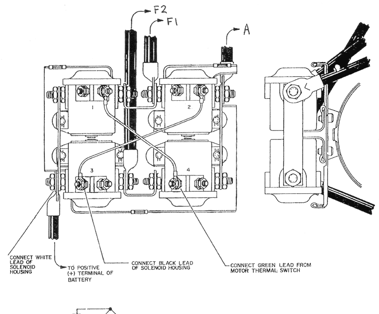
A 2 Solenoid Winch Wiring Diagram depicts the electrical connections for powering and controlling a winch equipped with two solenoids. In practice, this wiring scheme allows for the reversal of winch direction, making it suitable for applications such as lifting or pulling heavy loads.
This wiring diagram is significant as it ensures proper winch operation, prevents damage to components, and enhances safety. A pivotal historical development in winch technology was the introduction of electric solenoids, which replaced manual levers, offering greater precision and safety in load handling.
This article delves into the technical aspects of 2 Solenoid Winch Wiring Diagrams, covering circuit components, wiring configurations, troubleshooting techniques, and practical applications in various industries.
Understanding the essential aspects of a 2 Solenoid Winch Wiring Diagram is paramount for its proper installation, operation, and maintenance. These aspects encompass various dimensions related to the diagram, including its components, functionalities, and applications.
- Components: Solenoids, motor, controller, wiring
- Functionalities: Powering, controlling, reversing winch direction
- Circuitry: Electrical connections, circuit protection
- Safety: Preventing damage, ensuring safe operation
- Applications: Lifting, pulling, material handling
- Troubleshooting: Diagnosing and resolving issues
- Standards: Compliance with electrical codes
- Maintenance: Inspection, testing, repairs
These aspects are interconnected and contribute to the overall effectiveness and safety of the winch system. For instance, proper component selection and circuit design ensure reliable winch operation, while adherence to safety standards minimizes electrical hazards. Understanding these aspects empowers technicians and users to make informed decisions, perform effective troubleshooting, and ensure optimal winch performance.
Components
Within a 2 Solenoid Winch Wiring Diagram, the solenoids, motor, controller, and wiring play critical roles in the operation and control of the winch system. The solenoids serve as electromagnetic switches, activated by the controller to engage the motor and change the winch’s direction. The motor provides the mechanical power for lifting or pulling loads, while the controller acts as the central hub for regulating the system’s electrical functions.
The wiring serves as the backbone of the system, connecting the various components and facilitating the flow of electrical current. Proper selection and arrangement of these components are essential for safe and efficient winch operation. For instance, using appropriately rated solenoids and wiring ensures that the system can handle the required electrical loads without overheating or damage.
Understanding the relationship between these components is crucial for troubleshooting and maintaining winch systems. By identifying potential issues within each component and its connection to the overall wiring diagram, technicians can diagnose and resolve problems quickly and effectively. This understanding also enables informed decision-making during winch system design and installation, ensuring optimal performance and longevity.
Functionalities
Within the context of a 2 Solenoid Winch Wiring Diagram, the functionalities of powering, controlling, and reversing winch direction are central to its operation and effectiveness. These functionalities are achieved through the coordinated action of various components within the wiring diagram.
-
Powering the Winch:
The wiring diagram provides the electrical pathway for powering the winch motor, enabling it to generate the necessary torque for lifting or pulling loads. Proper wire sizing and connections ensure efficient power transmission and prevent overheating.
-
Controlling Winch Direction:
The solenoids, activated by the controller, determine the direction of winch rotation. By energizing the appropriate solenoid, the polarity of the motor’s electrical supply is reversed, causing the winch to rotate in the desired direction.
-
Reversing Winch Direction:
The ability to reverse the winch’s direction is crucial for load handling and positioning. The wiring diagram facilitates this functionality by allowing the solenoids to be energized in a sequence that changes the motor’s rotational direction.
-
Safety Interlocks:
The wiring diagram may incorporate safety interlocks to prevent simultaneous energization of both solenoids, which could damage the winch. These interlocks ensure proper sequencing and protect the system from electrical faults.
Collectively, these functionalities empower the winch operator with precise control over the winch’s operation, enabling efficient and safe load handling. Understanding these functionalities is crucial for proper winch installation, operation, and troubleshooting.
Circuitry
Within the context of a 2 Solenoid Winch Wiring Diagram, circuitry plays a critical role in ensuring proper electrical connections and safeguarding the system against potential hazards. The wiring diagram outlines the pathways for current flow, incorporates essential components for circuit protection, and establishes a framework for reliable winch operation.
-
Electrical Connections:
The wiring diagram specifies the connections between the various components of the winch system, including solenoids, motor, controller, and power source. Proper wire sizing and termination are crucial for minimizing voltage drops, preventing overheating, and ensuring efficient power transmission.
-
Fuses or Circuit Breakers:
These devices protect the winch system from excessive current flow that could damage components or cause electrical fires. They act as sacrificial elements, breaking the circuit when the current exceeds a predetermined threshold, preventing further damage.
-
Grounding:
The wiring diagram incorporates grounding connections to provide a low-resistance path for fault currents and protect against electrical shocks. Proper grounding ensures the safe operation of the winch and prevents damage to equipment.
-
Isolation and Shielding:
The wiring diagram may include provisions for isolating and shielding electrical connections to minimize electromagnetic interference (EMI) and ensure reliable signal transmission. This is particularly important in environments with high levels of electrical noise or where sensitive electronic components are present.
Collectively, these aspects of circuitry contribute to the safe and efficient operation of the 2 Solenoid Winch system. By understanding the role and implications of each component and connection, technicians can troubleshoot issues, perform maintenance, and ensure the winch system operates within its intended parameters.
Safety
Within the context of a 2 Solenoid Winch Wiring Diagram, safety measures are paramount to prevent damage to equipment and ensure the well-being of operators. The wiring diagram incorporates various provisions to protect against electrical hazards, mechanical failures, and improper operation.
-
Electrical Protection:
Fuses or circuit breakers safeguard the system against overcurrent conditions, preventing electrical fires and damage to components. Proper wire sizing and insulation minimize voltage drops and reduce the risk of overheating.
-
Mechanical Safety:
Wiring harnesses and conduit protect electrical connections from physical damage, preventing short circuits and ensuring reliable operation. Strain reliefs prevent excessive stress on wire terminations, reducing the risk of loose connections.
-
Grounding:
Grounding connections provide a low-resistance path for fault currents, protecting against electrical shocks and equipment damage. Proper grounding ensures the safe operation of the winch and complies with electrical safety codes.
-
Emergency Stop:
Emergency stop circuits allow for the immediate shutdown of the winch in case of an emergency. These circuits override other control inputs and quickly disconnect power to the motor, preventing accidents.
By incorporating these safety features, the 2 Solenoid Winch Wiring Diagram contributes to the safe and reliable operation of the winch system. Understanding these safety measures enables technicians and operators to identify potential hazards, implement appropriate safeguards, and respond effectively to emergency situations.
Applications
2 Solenoid Winch Wiring Diagrams play a crucial role in the operation and control of winches used for various lifting, pulling, and material handling applications. The specific wiring configuration enables precise control over the winch’s direction, making it suitable for a wide range of tasks in industries such as construction, manufacturing, and mining.
The cause-and-effect relationship between the applications and the wiring diagram is evident in the diagram’s design. The wiring diagram provides the electrical pathway for powering the winch motor and controlling the solenoids, which in turn determine the winch’s direction of rotation. This allows operators to lift, pull, and handle materials with precision and efficiency.
Real-life examples of applications include lifting heavy machinery onto construction sites, pulling vehicles out of ditches, and moving large objects in warehouses or factories. The versatility of the 2 Solenoid Winch Wiring Diagram makes it a valuable tool across various industries.
Understanding the connection between the applications and the wiring diagram is essential for proper winch installation, operation, and maintenance. By comprehending how the wiring diagram enables the winch to perform its intended functions, technicians can troubleshoot issues, ensure safe operation, and maximize the winch’s lifespan.
Troubleshooting
In the context of a 2 Solenoid Winch Wiring Diagram, troubleshooting plays a vital role in maintaining winch functionality and ensuring safe operation. The wiring diagram provides a roadmap for diagnosing and resolving issues that may arise during winch operation, enabling technicians to identify and address problems efficiently.
The cause-and-effect relationship between troubleshooting and the wiring diagram is evident. A thorough understanding of the wiring diagram allows technicians to trace electrical circuits, identify potential failure points, and determine the root cause of issues. This understanding empowers them to implement effective solutions, ranging from simple repairs to more complex component replacements.
Real-life examples of troubleshooting within a 2 Solenoid Winch Wiring Diagram include diagnosing open or short circuits, identifying faulty solenoids, and resolving motor control problems. These issues can manifest in various symptoms, such as the winch not responding to controls, intermittent operation, or abnormal noise or vibrations. By systematically troubleshooting the wiring diagram, technicians can pinpoint the source of the problem and take appropriate corrective actions.
The practical significance of troubleshooting in relation to the wiring diagram extends beyond resolving immediate issues. It contributes to preventive maintenance, enhances safety, and optimizes winch performance. By identifying and addressing potential problems early on, technicians can prevent minor issues from escalating into major failures, ensuring the winch’s reliability and longevity.
In summary, troubleshooting is an essential component of a 2 Solenoid Winch Wiring Diagram. It empowers technicians to diagnose and resolve issues effectively, ensuring safe and efficient winch operation. Understanding the connection between troubleshooting and the wiring diagram is crucial for maintaining winch functionality, preventing downtime, and maximizing its lifespan.
Standards
Within the context of a 2 Solenoid Winch Wiring Diagram, compliance with electrical codes is paramount to ensure the safe and reliable operation of the winch system. Electrical codes establish a set of guidelines and regulations that govern the design, installation, and maintenance of electrical systems, including winch wiring.
The relationship between standards and the wiring diagram is bidirectional. On the one hand, compliance with electrical codes directly influences the design of the wiring diagram. The diagram must adhere to the code requirements for wire sizing, circuit protection, and grounding, among other aspects. This ensures that the winch system operates within safe electrical parameters, minimizing the risk of electrical fires, shocks, and other hazards.
On the other hand, the wiring diagram serves as a tool for verifying compliance with electrical codes. By following the diagram, inspectors and technicians can assess whether the winch system has been installed and wired according to code requirements. This verification process helps ensure that the system meets safety standards and minimizes the risk of accidents or malfunctions.
Real-life examples of standards compliance within a 2 Solenoid Winch Wiring Diagram include proper wire sizing to handle the current draw of the winch motor, the use of appropriately rated fuses or circuit breakers for overcurrent protection, and the inclusion of a grounding connection to provide a low-resistance path for fault currents. These measures, guided by electrical codes, contribute to the overall safety and reliability of the winch system.
The practical significance of understanding the connection between standards and the wiring diagram lies in the ability to design, install, and maintain winch systems that meet safety requirements. By adhering to electrical codes and following the wiring diagram, technicians can ensure that the winch system operates as intended, minimizing the risk of accidents and maximizing its lifespan.
Maintenance
Within the context of a 2 Solenoid Winch Wiring Diagram, maintenance encompassing inspection, testing, and repairs plays a crucial role in ensuring the winch system’s safety, reliability, and optimal performance. Regular maintenance helps identify potential issues early on, preventing minor problems from escalating into major failures, and extending the winch’s lifespan.
The connection between maintenance and the wiring diagram is evident in several ways. Firstly, the wiring diagram provides a roadmap for technicians to systematically inspect and test the winch system’s electrical components. By following the diagram, they can verify the integrity of wires, connections, solenoids, and the motor, ensuring that the system operates within safe electrical parameters.
Secondly, the wiring diagram serves as a guide for troubleshooting and repairs. When a problem arises, technicians can refer to the diagram to identify the affected components and trace the electrical circuits to pinpoint the root cause of the issue. This understanding enables them to perform targeted repairs, replacing faulty components or addressing loose connections, restoring the winch system to proper working order.
Real-life examples of maintenance within a 2 Solenoid Winch Wiring Diagram include periodic inspections to check for loose connections, corrosion, or damaged wires; testing the solenoids to ensure proper operation; and performing load tests to verify the winch’s lifting capacity and identify any mechanical issues. These maintenance procedures, guided by the wiring diagram, contribute to the overall safety and reliability of the winch system.
The practical significance of understanding the connection between maintenance and the wiring diagram lies in the ability to develop effective maintenance plans and strategies. By following the diagram and adhering to recommended maintenance intervals, technicians can proactively identify and address potential problems, preventing costly downtime and ensuring the winch system operates at peak efficiency throughout its service life.


![]()


Related Posts


