3 Way Dimmer Wiring involves controlling a single light from two separate locations, allowing for convenient adjustment of light intensity. For instance, a bedroom can have switches by the door and bedside, enabling the user to dim the lights from either switch.
This wiring technique enhances usability and saves energy by precisely adjusting lighting. The introduction of solid-state dimmers in the 1960s revolutionized 3 Way Dimmer Wiring, providing enhanced control and reliability.
In this article, we will delve into the specifics of 3 Way Dimmer Wiring, exploring its components, wiring diagrams, and troubleshooting techniques.
Understanding the key aspects of 3 Way Dimmer Wiring is crucial for achieving optimal lighting control and energy efficiency. These aspects encompass various dimensions, ranging from the functional components to the wiring techniques.
- Components: Switches, dimmers, wiring
- Wiring Diagrams: Single-pole, three-way
- Voltage Compatibility: 120V, 240V
- Load Capacity: Wattage limitations
- Dimmer Types: Incandescent, LED, fluorescent
- Troubleshooting: Switch malfunctions, flickering
- Safety Considerations: Grounding, wire insulation
- Code Compliance: Electrical codes and standards
These aspects are interconnected, influencing the overall functionality and safety of 3 Way Dimmer Wiring. For instance, choosing the correct dimmer type based on the load capacity and compatibility with the lighting fixtures is essential to avoid overloading or damage. Additionally, proper grounding and adherence to electrical codes ensure a safe and reliable installation.
Components
Components: Switches, dimmers, and wiring are the cornerstone of 3 Way Dimmer Wiring, working in concert to facilitate control over lighting intensity from multiple locations. The switches serve as the user interface, allowing for turning the lights on/off and adjusting the brightness. Dimmers regulate the flow of electricity to the lighting fixtures, enabling smooth transitions in light intensity. Wiring connects these components, forming a closed circuit that allows for the transmission of electrical signals and power.
The interplay between these components is crucial for the effective operation of 3 Way Dimmer Wiring. Without switches, users would not be able to control the lights remotely, and without dimmers, they would be limited to simple on/off functionality. Proper wiring ensures that the electrical signals and power are transmitted efficiently and safely, preventing malfunctions and potential hazards.
In real-world applications, 3 Way Dimmer Wiring is commonly used in bedrooms, hallways, and living rooms, where the ability to control lighting from multiple locations enhances convenience and flexibility. For instance, a bedroom can have a switch by the door and another by the bedside, allowing users to adjust the lighting without having to get out of bed. Similarly, hallways can benefit from 3 Way Dimmer Wiring, enabling users to turn on the lights from the top of the stairs and then adjust the brightness as they walk down.
Understanding the connection between components: switches, dimmers, and wiring is essential for designing, installing, and troubleshooting 3 Way Dimmer Wiring systems. By carefully selecting and configuring these components, electricians and homeowners can create lighting systems that meet specific needs and preferences, enhancing comfort, energy efficiency, and overall ambiance.
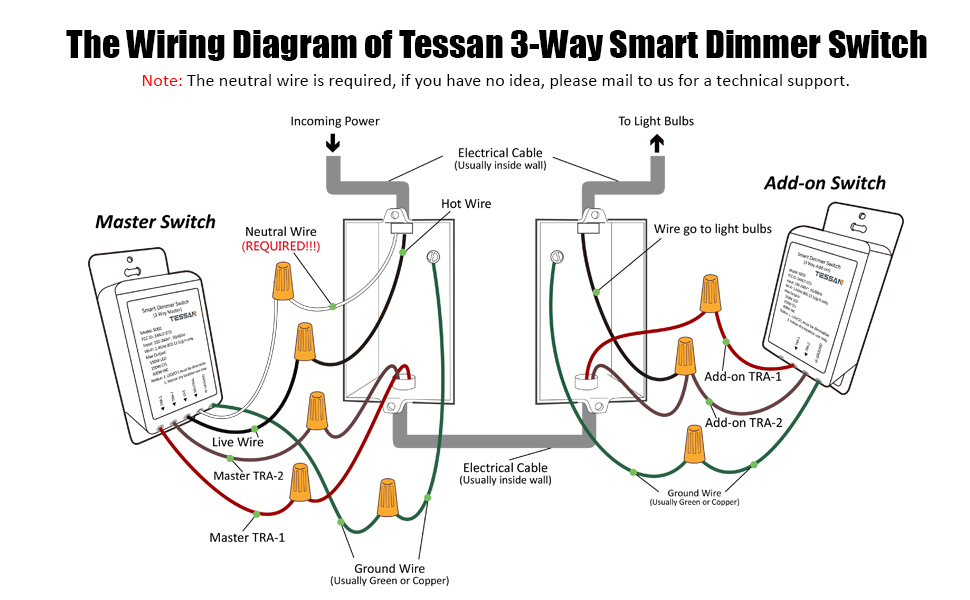
Wiring Diagrams
Wiring diagrams are crucial for understanding and installing 3 Way Dimmer Wiring systems. They provide a visual representation of the electrical connections between switches, dimmers, and lighting fixtures, ensuring proper functionality and safety.
-
Single-pole switches
Single-pole switches are used to control a light from a single location. They have two terminals, one for the incoming power and one for the outgoing power to the light. In a 3 Way Dimmer Wiring system, single-pole switches are typically used at the ends of the circuit.
-
Three-way switches
Three-way switches are used to control a light from two different locations. They have three terminals, one for the incoming power, one for the outgoing power to one location, and one for the outgoing power to the other location. In a 3 Way Dimmer Wiring system, three-way switches are typically used in the middle of the circuit.
-
Neutral wire
The neutral wire provides a return path for the electrical current. It is typically white or gray and is connected to the neutral terminal on the dimmer and the neutral terminals on the switches.
-
Ground wire
The ground wire provides a safety path for any stray electrical current. It is typically green or bare copper and is connected to the ground terminal on the dimmer and the ground terminals on the switches.
Understanding wiring diagrams for single-pole and three-way switches is essential for designing and installing 3 Way Dimmer Wiring systems. By following the correct wiring diagram, electricians and homeowners can ensure that the system is safe and functional, allowing for convenient control of lighting intensity from multiple locations.
Voltage Compatibility
In the realm of 3 Way Dimmer Wiring, voltage compatibility is paramount, influencing the selection of components and the overall functionality of the system. Understanding the differences between 120V and 240V compatibility is crucial for ensuring safety and optimal performance.
-
Voltage Rating
Dimmers and switches must be rated for the voltage of the circuit they will be installed in. Using a dimmer or switch with an incorrect voltage rating can lead to overheating, damage to the device, or even electrical fires. -
Lighting Fixture Compatibility
Lighting fixtures also have voltage ratings and must be compatible with the voltage of the circuit they will be connected to. Installing a lighting fixture with an incorrect voltage rating can result in the fixture not functioning properly or even becoming a safety hazard. -
Wiring Requirements
The wiring used in a 3 Way Dimmer Wiring system must be rated for the voltage of the circuit. Using wire with an incorrect voltage rating can lead to overheating, insulation breakdown, and potential electrical hazards. -
Circuit Protection
Circuit breakers and fuses are used to protect electrical circuits from overcurrent conditions. The amperage rating of the circuit protection device must be appropriate for the voltage and load of the circuit. Using a circuit protection device with an incorrect amperage rating can lead to nuisance tripping or, in the worst case, failure to protect the circuit from an overcurrent condition.
Understanding the voltage compatibility requirements of 3 Way Dimmer Wiring systems is essential for safe and reliable operation. By carefully considering the voltage ratings of dimmers, switches, lighting fixtures, and wiring, electricians and homeowners can ensure that the system is properly configured and functions as intended.
Load Capacity
In the context of 3 Way Dimmer Wiring, understanding load capacity and wattage limitations is critical for ensuring the safe and efficient operation of the system. Load capacity refers to the maximum amount of power that a dimmer switch can handle, typically measured in watts. Exceeding the load capacity of a dimmer switch can lead to overheating, damage to the dimmer, or even electrical fires.
When selecting a dimmer switch for a 3 Way Dimmer Wiring system, it is essential to consider the total wattage of the lighting fixtures that will be connected to the dimmer. The wattage of a lighting fixture is typically indicated on the fixture itself or in the manufacturer’s specifications. By adding up the wattage of all the lighting fixtures that will be connected to the dimmer, you can determine the total load that the dimmer will need to handle.
Real-life examples of load capacity limitations in 3 Way Dimmer Wiring systems include:
- Using a 600-watt dimmer switch to control a total of 750 watts of lighting fixtures. This would exceed the load capacity of the dimmer switch and could lead to overheating or damage.
- Connecting multiple high-wattage lighting fixtures, such as halogen or incandescent bulbs, to a dimmer switch that is only rated for a lower wattage. This could also exceed the load capacity of the dimmer switch and pose a safety hazard.
- Using a dimmer switch to control a lighting fixture that is not compatible with dimmers. This could damage the lighting fixture or the dimmer switch.
Practical applications of understanding load capacity and wattage limitations in 3 Way Dimmer Wiring include:
- Selecting the correct dimmer switch for a given application, ensuring that the load capacity of the dimmer is sufficient to handle the total wattage of the lighting fixtures.
- Avoiding overloading dimmer switches, which can lead to safety hazards and reduced lifespan of the dimmer.
- Choosing lighting fixtures that are compatible with dimmers, ensuring that the lighting fixtures will not be damaged when dimmed.
In summary, understanding load capacity and wattage limitations is a critical aspect of 3 Way Dimmer Wiring. By carefully considering the load capacity of dimmer switches and the wattage of lighting fixtures, electricians and homeowners can ensure the safe and efficient operation of 3 Way Dimmer Wiring systems.
Dimmer Types
Selecting the appropriate dimmer type is crucial in 3 Way Dimmer Wiring systems, as different lighting technologies have unique dimming characteristics and compatibility requirements. Understanding the specific types of dimmers available, including incandescent, LED, and fluorescent, is essential for achieving optimal performance and longevity of the lighting system.
-
Incandescent Dimmers
Incandescent dimmers are designed specifically for use with incandescent lighting fixtures. They operate by varying the amount of voltage supplied to the light bulb, resulting in changes in brightness. Incandescent dimmers are relatively inexpensive and widely available, but they are less efficient than other dimmer types and can generate heat.
-
LED Dimmers
LED dimmers are specifically designed for use with LED lighting fixtures. They operate by varying the amount of current supplied to the LED driver, resulting in changes in brightness. LED dimmers are more efficient than incandescent dimmers and do not generate heat. However, they are more expensive and may require specialized wiring.
-
Fluorescent Dimmers
Fluorescent dimmers are designed specifically for use with fluorescent lighting fixtures. They operate by varying the amount of voltage supplied to the ballast, resulting in changes in brightness. Fluorescent dimmers are less common than incandescent and LED dimmers, and they may not be compatible with all types of fluorescent lighting fixtures.
Choosing the correct dimmer type is essential for ensuring compatibility with the lighting fixtures and achieving the desired dimming performance. Incandescent dimmers are suitable for incandescent lighting fixtures, LED dimmers are suitable for LED lighting fixtures, and fluorescent dimmers are suitable for fluorescent lighting fixtures. Using the wrong type of dimmer can lead to flickering, buzzing, or even damage to the lighting fixtures or dimmer.
Troubleshooting
In the realm of 3 Way Dimmer Wiring, troubleshooting switch malfunctions and flickering is a critical aspect of maintaining a functional and aesthetically pleasing lighting system. These issues can manifest in various forms, from complete switch failure to intermittent flickering, and can be caused by a range of factors.
-
Faulty Wiring
Loose or damaged wiring connections can disrupt the flow of electricity, leading to switch malfunctions or flickering lights. This can occur due to improper installation, wear and tear, or external factors such as pests or water damage.
-
Loose Switch Terminals
Over time, the terminals on switches can become loose, causing intermittent contact and flickering lights. This is especially common in older switches or those that have been frequently used.
-
Defective Switch
Switches can fail due to manufacturing defects, excessive wear, or power surges. A defective switch may exhibit various symptoms, including complete failure, flickering, or erratic operation.
-
Incompatibility
Using a switch that is not compatible with the dimmer or lighting fixtures can lead to flickering or other issues. This can occur when mixing different brands or types of switches, or when using switches that are not rated for the load or voltage of the lighting system.
Troubleshooting switch malfunctions and flickering in 3 Way Dimmer Wiring requires a systematic approach. Electricians or homeowners can begin by checking the wiring connections, ensuring that they are secure and undamaged. Next, the switch terminals should be inspected for any signs of looseness or damage. If the issue persists, the switch itself may need to be replaced. Finally, it is important to verify the compatibility of the switch with the dimmer and lighting fixtures to rule out any potential mismatches.
Safety Considerations
In the context of 3 Way Dimmer Wiring, safety considerations, particularly grounding and wire insulation, are paramount for ensuring the safe and reliable operation of the electrical system. Grounding provides a low-resistance path for electrical current to flow in the event of a fault, protecting users from electrical shocks and preventing damage to equipment. Wire insulation serves as a protective layer around electrical wires, preventing short circuits and fires.
Grounding is achieved by connecting the metal housing of electrical devices, such as switches and dimmers, to the ground wire in the electrical circuit. This ground wire is typically identified by its green or bare copper color and is connected to the grounding bus in the electrical panel. In the event of a fault, such as a short circuit, the electrical current will flow through the ground wire and back to the electrical panel, preventing it from flowing through the user or the device itself.
Wire insulation is also critical for safety in 3 Way Dimmer Wiring. Electrical wires are typically coated with a non-conductive material, such as PVC or rubber, to prevent electrical current from escaping and causing shocks or fires. Proper wire insulation ensures that electrical current flows only through the intended path, preventing short circuits and ensuring the safe operation of the system.
Examples of the practical applications of grounding and wire insulation in 3 Way Dimmer Wiring include:
- Grounding the metal faceplate of a switch prevents electrical shocks if the switch becomes energized due to a fault.
- Insulating the wires connecting the switch, dimmer, and lighting fixture prevents short circuits and fires if the wires come into contact with each other or other conductive materials.
Understanding the importance of safety considerations, grounding, and wire insulation, in 3 Way Dimmer Wiring is essential for ensuring the safe and reliable operation of electrical systems. By adhering to proper grounding and insulation practices, electricians and homeowners can minimize the risk of electrical accidents and protect both people and property.
Code Compliance
Within the realm of 3 Way Dimmer Wiring, understanding and adhering to electrical codes and standards is paramount to ensure safety, reliability, and compliance with regulatory requirements. These codes and standards provide a comprehensive set of guidelines for the design, installation, and maintenance of electrical systems, ensuring that they meet minimum safety standards and operate as intended.
-
Wiring Methods
Electrical codes specify the proper methods for installing electrical wiring, including the types of wires, their allowable current carrying capacities, and the routes by which they can be run. This ensures that wiring is installed in a safe and reliable manner, minimizing the risk of electrical fires and other hazards.
-
Device Installation
Codes also provide guidelines for the installation of electrical devices, such as switches, dimmers, and lighting fixtures. These guidelines cover aspects such as proper grounding, mounting methods, and spacing requirements. Following these guidelines ensures that devices are installed securely and function properly.
-
Circuit Protection
Electrical codes require the use of circuit protection devices, such as fuses and circuit breakers, to protect electrical circuits from overcurrent conditions. These devices are designed to interrupt the flow of electricity if the current exceeds a safe level, preventing damage to wiring and equipment.
-
Inspection and Maintenance
Regular inspection and maintenance of electrical systems are crucial for ensuring ongoing safety and reliability. Codes provide guidelines for the frequency and scope of inspections, as well as the qualifications of personnel who can perform these tasks. Proper maintenance helps to identify and address potential issues before they become major problems.
By adhering to electrical codes and standards, electricians and homeowners can ensure that 3 Way Dimmer Wiring systems are installed and maintained in a safe and compliant manner. This not only protects people and property from electrical hazards but also helps to ensure that the system operates as intended, providing convenient and reliable control over lighting.


Related Posts


