A 220 Breaker Box Wiring Diagram is a detailed graphical representation of the electrical connections within a 220-volt electrical panel. It outlines the layout and configuration of circuit breakers, wires, and other components, providing a clear understanding of the power distribution system within a building or structure.
The core function of a Breaker Box Wiring Diagram is to ensure the safe and efficient operation of the electrical system. It acts as a roadmap for electricians and homeowners, providing a visual guide to troubleshoot issues, plan upgrades, or perform maintenance tasks. By knowing the exact location and connections of each component, electrical professionals can quickly identify and resolve any problems, minimizing the risk of electrical hazards.
Transitioning to the main article topics, this comprehensive guide will delve deeper into the intricate details of 220 Breaker Box Wiring Diagrams, including their importance in electrical safety, the benefits of using them, and the historical context that has shaped their development. We will explore real-world applications, industry best practices, and advancements in electrical technology that have made these diagrams an indispensable tool in modern electrical installations.
Understanding the key aspects of a 220 Breaker Box Wiring Diagram is paramount for electrical professionals and homeowners alike. These diagrams provide a comprehensive overview of the electrical system, ensuring safety, efficiency, and ease of maintenance. Here are eight key aspects to consider:
- Circuit Breaker Locations: Diagrams clearly indicate the location of each circuit breaker within the panel, allowing for quick identification and troubleshooting.
- Wire Connections: Diagrams detail the connections between circuit breakers, wires, and other components, ensuring proper power distribution.
- Amperage and Voltage Ratings: Diagrams specify the amperage and voltage ratings of each circuit breaker, providing essential information for load calculations and safety.
- Grounding and Neutral Connections: Diagrams show the grounding and neutral connections within the panel, ensuring proper electrical safety and grounding.
- Bus Bar Configuration: Diagrams illustrate the layout of the bus bars within the panel, providing insight into the power distribution and capacity of the system.
- Knockout Locations: Diagrams indicate the knockout locations for conduit and wiring, assisting in the planning and installation of new circuits.
- Panel Size and Capacity: Diagrams specify the size and capacity of the electrical panel, helping determine if it can accommodate additional circuits or upgrades.
- Compliance with Electrical Codes: Diagrams ensure compliance with electrical codes and standards, promoting electrical safety and reducing the risk of hazards.
These aspects work together to provide a comprehensive understanding of the 220 Breaker Box Wiring Diagram. By understanding these key aspects, electricians and homeowners can ensure the safe and efficient operation of their electrical systems.
Circuit Breaker Locations
In the context of a 220 Breaker Box Wiring Diagram, the precise location of each circuit breaker is a crucial component for efficient electrical system management and troubleshooting. These diagrams provide a clear visual representation of the layout within the electrical panel, enabling electricians and homeowners to quickly identify and access specific circuit breakers. This is particularly important when troubleshooting electrical issues, as it allows for the isolation of affected circuits without disrupting the entire system.
For instance, if a particular outlet or appliance is not functioning correctly, the wiring diagram will help identify the corresponding circuit breaker that controls its power supply. This allows for targeted troubleshooting, such as checking for tripped breakers or loose connections, without having to search through multiple circuits or the entire panel.
Furthermore, knowing the exact location of circuit breakers is essential for maintenance and upgrades. When adding new circuits or replacing faulty components, the wiring diagram provides a clear reference for determining the appropriate circuit breaker size and capacity. This ensures the safe and efficient operation of the electrical system, preventing overloads and potential hazards.
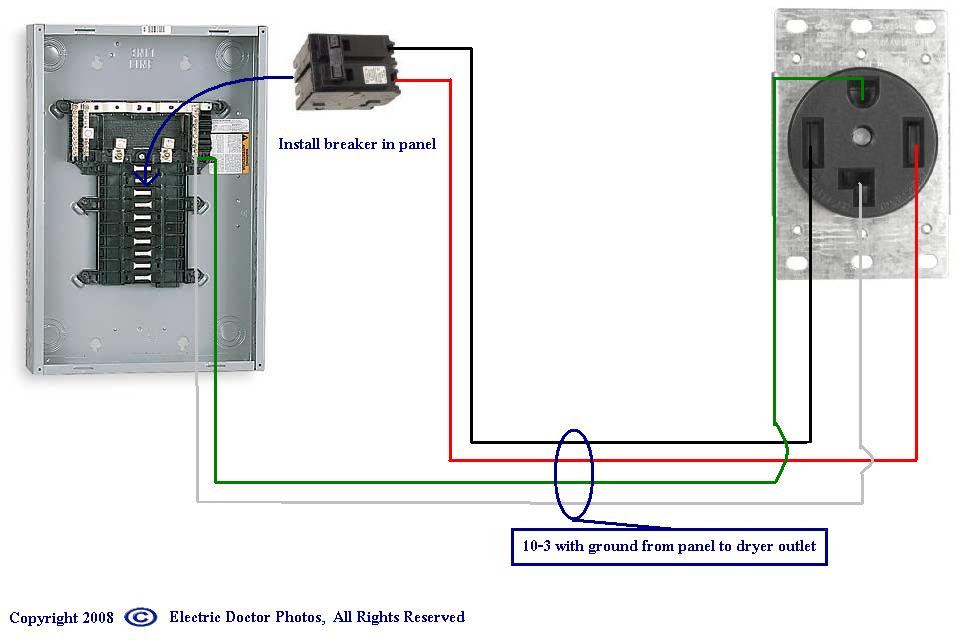
Wire Connections
Within the context of a 220 Breaker Box Wiring Diagram, wire connections play a pivotal role in ensuring the safe and efficient distribution of electrical power throughout a building or structure. These diagrams provide a detailed representation of how circuit breakers, wires, and other components are interconnected, offering valuable insights for electrical professionals and homeowners alike.
- Circuit Breaker Connections: Wiring diagrams clearly illustrate the connections between circuit breakers and the electrical bus bars within the panel. This information is crucial for understanding how power is distributed to different circuits and for troubleshooting any tripped or faulty breakers.
- Wire Sizing and Routing: Diagrams specify the appropriate wire sizes and routing for each circuit, ensuring that wires can safely handle the electrical load and minimize voltage drop. This aspect is critical for preventing overheating, electrical fires, and other hazards.
- Grounding and Neutral Connections: Proper grounding and neutral connections are essential for electrical safety. Wiring diagrams show how these connections are made within the panel, providing a clear understanding of the grounding system and reducing the risk of electrical shocks.
- Component Interconnections: In addition to circuit breakers and wires, diagrams also depict the connections between other components within the panel, such as surge protectors, transformers, and metering devices. This comprehensive view facilitates the understanding of the overall system functionality and simplifies troubleshooting efforts.
Overall, the detailed representation of wire connections in 220 Breaker Box Wiring Diagrams empowers electricians and homeowners with the knowledge necessary to ensure the safe and reliable operation of their electrical systems. These diagrams serve as an indispensable tool for troubleshooting, maintenance, and upgrades, contributing to the overall safety and efficiency of electrical installations.
Amperage and Voltage Ratings
Within the context of a 220 Breaker Box Wiring Diagram, the amperage and voltage ratings of each circuit breaker are crucial pieces of information that contribute to the overall safety and efficiency of the electrical system. These ratings directly impact the load calculations and the selection of appropriate circuit breakers for each circuit.
The amperage rating of a circuit breaker determines the maximum amount of current that can safely flow through the circuit without tripping the breaker. Exceeding the amperage rating can lead to overheating, damage to electrical components, and potential fire hazards. Wiring diagrams provide clear specifications of the amperage rating for each circuit breaker, ensuring that electricians and homeowners can select the correct breaker size for the intended load.
Similarly, the voltage rating of a circuit breaker indicates the maximum voltage that the breaker can safely handle. Using a circuit breaker with an insufficient voltage rating can lead to premature failure or electrical hazards. Wiring diagrams specify the voltage rating for each circuit breaker, allowing for the proper selection and installation of breakers that are compatible with the electrical system’s voltage.
The importance of accurate load calculations cannot be overstated. Overloading a circuit can trip the breaker, interrupting power to essential appliances or devices. Conversely, using a circuit breaker with an excessively high amperage rating can compromise safety, as it may not trip quickly enough to prevent overheating or electrical fires.
In practice, electricians and homeowners rely on 220 Breaker Box Wiring Diagrams to determine the appropriate amperage and voltage ratings for each circuit. These diagrams provide a comprehensive overview of the electrical system, including the location and ratings of all circuit breakers. By carefully considering the load requirements and electrical characteristics of each circuit, electricians can ensure that the correct circuit breakers are installed, promoting electrical safety and preventing potential hazards.
Grounding and Neutral Connections
Grounding and neutral connections are critical components of any electrical system, and 220 Breaker Box Wiring Diagrams play a vital role in ensuring that these connections are made correctly. Grounding connections provide a low-resistance path for electrical current to flow back to the source, while neutral connections provide a reference point for the electrical system. Without proper grounding and neutral connections, electrical systems can be dangerous and prone to electrical faults.
220 Breaker Box Wiring Diagrams show the location of all grounding and neutral connections within the panel. This information is essential for electricians when they are installing or troubleshooting an electrical system. By following the diagram, electricians can ensure that all connections are made correctly and that the system is safe to operate.
There are several real-life examples of the importance of grounding and neutral connections. For instance, in 2017, a house fire in California was caused by a faulty neutral connection. The loose connection caused an electrical arc that ignited nearby combustible materials. The fire caused extensive damage to the house and its contents.
Another example of the importance of grounding and neutral connections is the electrical shock hazard. If an electrical appliance is not properly grounded, it can become energized if there is a fault in the system. This can pose a serious shock hazard to anyone who comes into contact with the appliance.
Understanding the grounding and neutral connections in a 220 Breaker Box Wiring Diagram is essential for ensuring the safety and proper operation of an electrical system. By following the diagram, electricians can ensure that all connections are made correctly and that the system is safe to operate.
Bus Bar Configuration
Within the context of a 220 Breaker Box Wiring Diagram, the bus bar configuration plays a pivotal role in understanding the power distribution and capacity of the electrical system. Bus bars are conductive metal strips that distribute electrical power throughout the panel, serving as the backbone of the system. Understanding their layout and arrangement is crucial for ensuring the safe and efficient operation of the electrical system.
- Power Distribution: Diagrams illustrate how the bus bars distribute power to individual circuit breakers. This information is essential for determining the load capacity of each circuit and ensuring that the system can handle the electrical demands of the connected appliances and devices.
- Panel Capacity: The bus bar configuration provides insights into the overall capacity of the electrical panel. By understanding the number and size of the bus bars, electricians can determine the maximum amperage and voltage that the panel can safely handle.
- Circuit Breaker Arrangement: Wiring diagrams show the arrangement of circuit breakers in relation to the bus bars. This helps electricians identify which circuits are connected to each bus bar, simplifying troubleshooting and maintenance tasks.
- Grounding and Neutral Connections: Diagrams also depict the location of grounding and neutral connections on the bus bars. Proper grounding and neutral connections are essential for electrical safety and preventing electrical faults.
In summary, the bus bar configuration in a 220 Breaker Box Wiring Diagram provides valuable insights into the power distribution, capacity, and safety aspects of the electrical system. By understanding the layout and arrangement of the bus bars, electricians can make informed decisions about circuit breaker selection, load balancing, and overall system design, ensuring the safe and reliable operation of the electrical system.
Knockout Locations
Knockout locations are a crucial aspect of 220 Breaker Box Wiring Diagrams, providing valuable information for electrical professionals and homeowners alike. These diagrams clearly mark the designated areas on the electrical panel enclosure where knockouts can be removed to accommodate conduit and wiring during the installation or modification of electrical circuits.
- Planning and Design: Knockout locations enable electricians to plan and design the layout of new circuits, ensuring that there is sufficient space for conduit and wiring to enter and exit the panel safely and efficiently.
- Conduit and Wire Sizing: Diagrams specify the knockout sizes, which correspond to the appropriate conduit and wire sizes. This information helps electricians select the correct materials for the intended electrical load.
- Code Compliance: Knockout locations are designed to comply with electrical codes and standards. Using knockouts as designated ensures proper installation and reduces the risk of electrical hazards.
- Safety and Protection: Knockouts provide a secure and protected entry point for conduit and wiring, preventing damage to the electrical panel and ensuring the longevity of the electrical system.
Knockout locations in 220 Breaker Box Wiring Diagrams play a vital role in ensuring the safe and efficient installation, modification, and maintenance of electrical circuits. By understanding and utilizing the knockout locations specified in these diagrams, electricians can ensure that electrical systems operate reliably and meet all applicable safety codes and standards.
Panel Size and Capacity
Within the context of 220 Breaker Box Wiring Diagrams, understanding the size and capacity of the electrical panel is crucial for determining its capability to accommodate additional circuits or upgrades. These diagrams provide detailed specifications and dimensions of the panel, ensuring that electrical professionals and homeowners can make informed decisions about the system’s capabilities and limitations.
- Panel Dimensions and Space: Wiring diagrams clearly indicate the physical dimensions of the electrical panel, including its height, width, and depth. This information is essential for planning and ensuring that the panel can fit into the designated space and accommodate the necessary components.
- Circuit Capacity: Diagrams specify the maximum number of circuits that the panel can support. This capacity is determined by the number and amperage rating of the circuit breakers that can be installed in the panel.
- Load Calculations: Understanding the panel’s capacity helps electricians perform load calculations to determine if the panel can handle the total electrical load of the connected appliances and devices. Exceeding the panel’s capacity can lead to overloading and potential safety hazards.
- Future Expansion: Wiring diagrams provide insights into the potential for future expansion of the electrical system. By considering the panel’s size, capacity, and available knockout locations, electricians can plan for the addition of new circuits or upgrades in the future.
In summary, the panel size and capacity information provided in 220 Breaker Box Wiring Diagrams empower electrical professionals and homeowners with the knowledge necessary to assess the capabilities of the electrical panel. By carefully considering these factors, they can ensure that the panel can safely and efficiently meet the current and future electrical demands of the building or structure.
Compliance with Electrical Codes
In the context of 220 Breaker Box Wiring Diagrams, compliance with electrical codes and standards is paramount for ensuring the safety and integrity of electrical systems. These diagrams serve as a valuable tool for electrical professionals and homeowners alike, providing clear guidelines for the installation, maintenance, and modification of electrical circuits.
- Adherence to Safety Standards: Wiring diagrams ensure adherence to established electrical codes and standards, such as the National Electrical Code (NEC) and local building codes. By following these guidelines, electricians can minimize the risk of electrical fires, shocks, and other hazards.
- Proper Component Selection: Diagrams specify the appropriate circuit breakers, wires, and other components based on the electrical load and applicable codes. This helps prevent overloading and ensures that the electrical system operates within its intended parameters.
- Safe Installation Practices: Wiring diagrams provide detailed instructions for the proper installation of electrical components, including wire routing, grounding, and bonding. Following these instructions helps ensure a safe and reliable electrical system.
- Inspection and Approval: In many jurisdictions, electrical installations must be inspected and approved by a qualified electrical inspector. Wiring diagrams serve as a reference document for inspectors to verify compliance with electrical codes and standards.
By promoting compliance with electrical codes and standards, 220 Breaker Box Wiring Diagrams play a vital role in safeguarding the safety and efficiency of electrical systems. They empower electrical professionals and homeowners with the knowledge necessary to design, install, and maintain electrical systems that meet the highest safety standards.


Related Posts


