A Kicker Hideaway Wiring Diagram outlines the electrical connections for installing a Kicker brand Hideaway subwoofer system, often used in vehicles to enhance the sound system. These diagrams provide step-by-step instructions, identifying wire colors, connection points, and component placement.
Hideaway Wiring Diagrams are crucial for ensuring proper subwoofer operation, safety, and optimal performance. They minimize the risk of electrical shorts, damage to components, and provide a clear understanding of the system’s wiring configuration. The development of pre-designed diagrams by manufacturers simplifies the installation process, reducing complexity and potential errors.
This article delves into the specifics of Kicker Hideaway Wiring Diagrams, including detailed explanations of wire connections, troubleshooting tips, and compatibility considerations. By understanding these diagrams, enthusiasts can effectively enhance their vehicle’s audio systems with a seamless and reliable subwoofer installation.
Understanding the essential aspects of a Kicker Hideaway Wiring Diagram is crucial for ensuring a successful and safe subwoofer installation. These diagrams outline the electrical connections and provide clear instructions for integrating the subwoofer system into a vehicle’s audio setup.
- Compatibility: Ensuring the diagram matches the specific Kicker Hideaway subwoofer model and vehicle.
- Wire Gauge: Understanding the appropriate wire thickness for power, ground, and signal connections.
- Color Coding: Identifying the standardized wire colors for positive, negative, and remote turn-on.
- Power and Ground Connections: Locating the appropriate power and ground points in the vehicle.
- Remote Turn-On: Connecting to the vehicle’s audio system to trigger the subwoofer’s operation.
- Signal Input: Choosing the correct input type (line-level or speaker-level) and connecting to the audio source.
- Crossover Settings: Adjusting the crossover frequency to optimize subwoofer performance based on the vehicle’s acoustics.
- Gain Control: Setting the appropriate gain level to balance the subwoofer’s output with the rest of the audio system.
- Enclosure Specifications: Following the recommended enclosure size and type for optimal subwoofer performance.
- Troubleshooting: Identifying potential issues and providing solutions for common wiring problems.
These aspects are interconnected and crucial for achieving a seamless and effective subwoofer installation. By understanding and following the Kicker Hideaway Wiring Diagram, enthusiasts can ensure the proper functioning, safety, and optimal performance of their vehicle’s audio system.
Compatibility
Within the context of “Kicker Hideaway Wiring Diagram,” compatibility plays a crucial role. Ensuring the diagram aligns with the specific Kicker Hideaway subwoofer model and vehicle is fundamental for a successful installation and optimal performance.
- Subwoofer Model: Matching the diagram to the specific Kicker Hideaway subwoofer model is vital. Different models may have unique wiring configurations, power requirements, and impedance characteristics.
- Vehicle Compatibility: Considering the vehicle’s electrical system and audio setup is essential. The diagram should account for the vehicle’s specific voltage, ground points, and audio source connections.
- Enclosure Type: The wiring diagram should align with the type of enclosure used for the subwoofer. Sealed and ported enclosures have different wiring requirements.
- Amplifier Compatibility: If an external amplifier is used, the diagram should match the amplifier’s specifications, including power output, impedance, and input sensitivity.
Understanding and adhering to compatibility guidelines ensure that the Kicker Hideaway subwoofer system integrates seamlessly with the vehicle’s audio setup, delivering optimal performance, reliability, and safety. Overlooking compatibility can lead to improper operation, damage to components, or subpar sound quality.
Wire Gauge
In the context of a Kicker Hideaway Wiring Diagram, wire gauge plays a crucial role in ensuring the efficient and safe operation of the subwoofer system. Selecting the correct wire thickness for power, ground, and signal connections is essential for optimal performance and longevity.
- Power Wire: The power wire carries the electrical current from the vehicle’s battery to the subwoofer amplifier. Using an adequately thick power wire (typically 8-gauge or 4-gauge) minimizes voltage drop, ensuring that the amplifier receives sufficient power for optimal performance.
- Ground Wire: The ground wire provides a low-resistance path for electrical current to return to the vehicle’s chassis. A proper ground connection is crucial for preventing electrical noise and ensuring the stability of the subwoofer system. The ground wire should be of the same gauge as the power wire.
- Signal Wire: The signal wire carries the audio signal from the vehicle’s head unit or amplifier to the subwoofer amplifier. While signal wires typically require a smaller gauge (16-gauge or 18-gauge), using high-quality shielded cables minimizes signal interference and ensures clean audio reproduction.
- Implications: Using undersized wires can lead to excessive voltage drop, power loss, and potential overheating. Conversely, oversized wires, while less common, can be more expensive and less flexible. Following the recommendations provided in the Kicker Hideaway Wiring Diagram ensures the selection of appropriate wire gauges for optimal performance and safety.
Understanding and adhering to the wire gauge specifications outlined in the Kicker Hideaway Wiring Diagram is essential for achieving a seamless and effective subwoofer installation. Proper wire selection and installation contribute to a reliable, high-quality audio experience in the vehicle.
Color Coding
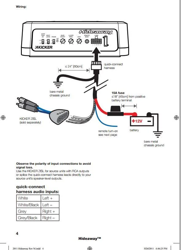
Within the context of a Kicker Hideaway Wiring Diagram, color coding plays a pivotal role in ensuring proper electrical connections and simplifying the installation process. The use of standardized wire colors for positive, negative, and remote turn-on facilitates the identification and connection of wires, minimizing the risk of errors and ensuring the safe and efficient operation of the subwoofer system.
- Power Wire: Positive power wires are typically colored red, indicating that they carry electrical current from the vehicle’s battery to the subwoofer amplifier.
- Ground Wire: Negative ground wires are usually black, signifying their role in providing a low-resistance path for electrical current to return to the vehicle’s chassis.
- Remote Turn-On: Remote turn-on wires are often blue, signaling their function in triggering the subwoofer amplifier to turn on when the vehicle’s audio system is activated.
- Signal Wires: Signal wires carrying audio signals to the subwoofer amplifier may vary in color, but they typically have striped or shielded insulation to minimize interference.
Adhering to the standardized color coding outlined in the Kicker Hideaway Wiring Diagram ensures a consistent and reliable electrical connection throughout the subwoofer system. This color coding is crucial for preventing misconnections, reducing the likelihood of electrical shorts, and ensuring optimal performance and longevity of the subwoofer system.
Power and Ground Connections
In the context of a Kicker Hideaway Wiring Diagram, establishing proper power and ground connections is paramount for ensuring the reliable and efficient operation of the subwoofer system. The power connection provides the electrical current necessary to drive the subwoofer amplifier, while the ground connection completes the electrical circuit, allowing current to flow back to the vehicle’s chassis.
The Kicker Hideaway Wiring Diagram meticulously outlines the specific locations within the vehicle where these connections should be made. These designated points are carefully chosen to provide optimal electrical conductivity and minimize potential interference or noise. By adhering to the diagram’s instructions, installers can ensure that the subwoofer system receives a stable and adequate power supply, resulting in improved performance, reduced distortion, and enhanced sound quality.
Moreover, proper power and ground connections are crucial for safety. Loose or improperly secured connections can lead to electrical shorts, fires, or damage to the subwoofer system or other vehicle components. The Kicker Hideaway Wiring Diagram provides clear guidance on the proper techniques for making these connections, including the use of appropriate connectors, wire gauges, and insulation.
Remote Turn-On
Within the context of a Kicker Hideaway Wiring Diagram, the remote turn-on connection plays a critical role in ensuring seamless integration between the subwoofer system and the vehicle’s audio system. This connection allows the subwoofer amplifier to automatically turn on or off in conjunction with the vehicle’s head unit, eliminating the need for manual operation.
The Kicker Hideaway Wiring Diagram meticulously outlines the process of connecting the remote turn-on wire from the subwoofer amplifier to a suitable source in the vehicle’s audio system. This source is typically a designated remote turn-on output on the head unit or an accessory wire that becomes active when the audio system is turned on. By establishing this connection, the subwoofer system can be configured to power on and off automatically, following the status of the vehicle’s audio system. This not only enhances convenience but also optimizes the subwoofer’s performance and lifespan.
Real-life examples of remote turn-on connections in Kicker Hideaway Wiring Diagrams include connecting to the head unit’s remote turn-on output or tapping into the vehicle’s accessory wire, such as the one powering the cigarette lighter socket. These connections ensure that the subwoofer system is synchronized with the vehicle’s audio system, providing an immersive and responsive audio experience. Understanding the importance of remote turn-on connections empowers installers to configure subwoofer systems that seamlessly integrate with the vehicle’s electronics.
Signal Input
Signal Input, encompassing the choice of input type and connection to the audio source, plays a crucial role in the Kicker Hideaway Wiring Diagram. The input type determines the signal’s characteristics, while the connection method ensures proper signal transmission to the subwoofer amplifier. Understanding this connection is essential for achieving optimal audio performance and system integration.
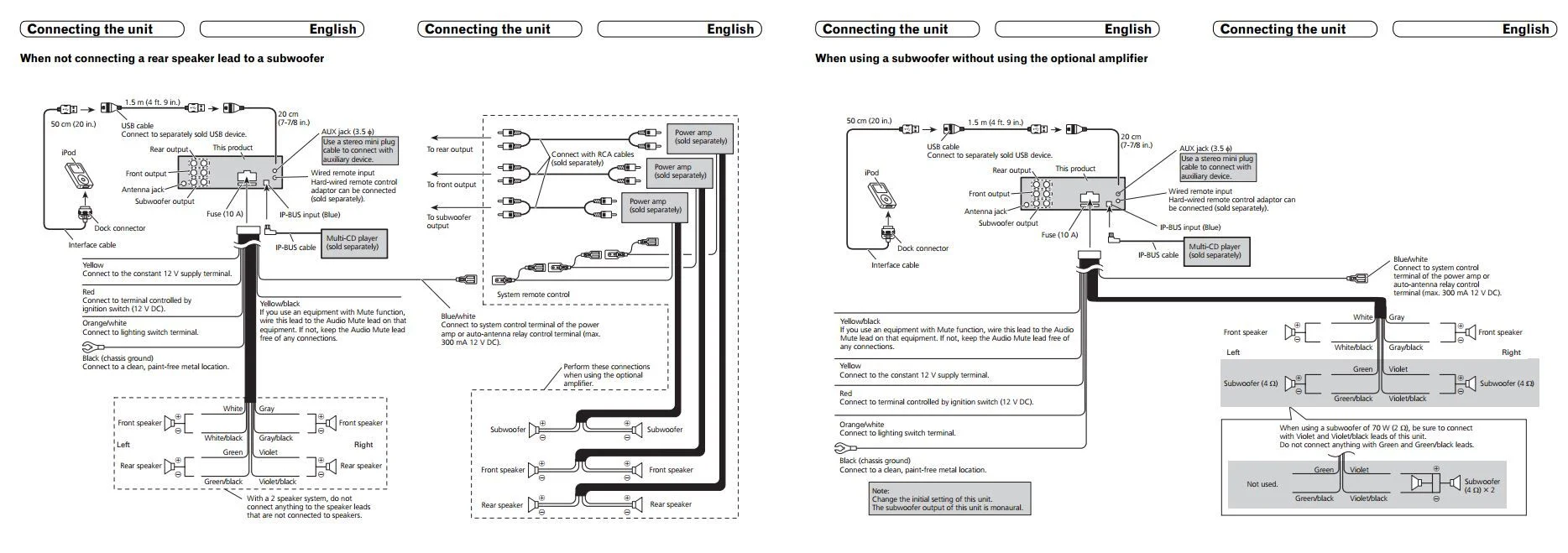
The Kicker Hideaway Wiring Diagram guides installers in selecting the appropriate input type based on the available audio source. Line-level inputs are typically used for connecting to head units or preamp outputs, providing a low-power signal that requires amplification. Speaker-level inputs, on the other hand, are designed to connect directly to speaker wires, handling higher power signals without the need for external amplification. Choosing the correct input type ensures proper signal matching and prevents potential damage to the subwoofer amplifier.
Real-life examples of signal input connections in the Kicker Hideaway Wiring Diagram include connecting to the head unit’s RCA outputs using line-level inputs or tapping into the vehicle’s speaker wires using speaker-level inputs. These connections allow the subwoofer system to receive audio signals from the vehicle’s audio system, enabling seamless integration and synchronized operation.
Understanding the importance of signal input in the Kicker Hideaway Wiring Diagram empowers installers and enthusiasts to configure subwoofer systems that deliver exceptional audio quality and functionality. By selecting the appropriate input type and making proper connections, they can optimize signal transfer, minimize distortion, and ensure the subwoofer system operates at its full potential.
Crossover Settings
Within the context of “Kicker Hideaway Wiring Diagram,” crossover settings play a vital role in tailoring the subwoofer’s performance to the specific acoustics of the vehicle. Adjusting the crossover frequency allows for seamless integration with the vehicle’s existing audio system, optimizing sound quality and enhancing the overall listening experience.
- Crossover Type: The type of crossover, such as low-pass or high-pass, determines the frequency range directed to the subwoofer. Choosing the appropriate crossover type ensures that the subwoofer reproduces only the desired frequency range, avoiding overlap or cancellation with other speakers.
- Crossover Frequency: The crossover frequency defines the point at which the subwoofer takes over from the main speakers. Setting the optimal crossover frequency depends on factors such as the subwoofer’s size, enclosure type, and the vehicle’s acoustics. Proper adjustment ensures a smooth transition between speakers, eliminating gaps or peaks in the frequency response.
- Slope: The slope of the crossover determines the rate at which the signal is attenuated above or below the crossover frequency. A steeper slope provides a sharper cutoff, while a gentler slope allows for a more gradual transition. Selecting the appropriate slope optimizes the subwoofer’s integration with the vehicle’s acoustics.
- Phase Adjustment: Phase adjustment aligns the subwoofer’s output with the main speakers, ensuring coherent sound reproduction. Improper phase alignment can result in cancellation or reinforcement at certain frequencies, affecting the overall sound quality. Adjusting the phase ensures that the subwoofer blends seamlessly with the rest of the audio system.
Understanding and optimizing crossover settings empower installers and enthusiasts to achieve a well-integrated and impactful subwoofer system. By carefully considering the vehicle’s acoustics and the subwoofer’s characteristics, they can tailor the crossover settings to create a cohesive and immersive audio experience.
Gain Control
Within the context of “Kicker Hideaway Wiring Diagram,” gain control plays a crucial role in optimizing the subwoofer’s performance and achieving a well-balanced audio experience. Setting the appropriate gain level ensures that the subwoofer blends seamlessly with the rest of the audio system, avoiding overpowering or underpowering.
- Signal Matching: Gain control allows for matching the subwoofer’s output level to the signal strength of the audio source. This ensures that the subwoofer reproduces the audio content accurately, without distortion or clipping.
- Level Adjustment: The gain level can be adjusted to compensate for differences in speaker sensitivity, enclosure type, and listening preferences. This flexibility enables installers to finetune the subwoofer’s output to suit the specific vehicle acoustics and personal tastes.
- Protection: Setting the proper gain level protects the subwoofer from damage caused by excessive power. When the gain is set too high, the subwoofer may be subjected to overdriven signals, leading to voice coil overheating and potential failure.
- Optimization: Gain control allows for optimizing the subwoofer’s integration with the vehicle’s audio system. By adjusting the gain, installers can ensure a smooth transition between the subwoofer and the main speakers, creating a cohesive and immersive sound experience.
Understanding and properly setting the gain control is essential for achieving the best possible performance from a Kicker Hideaway subwoofer system. By carefully considering the factors mentioned above, installers and enthusiasts can optimize the subwoofer’s output, balancing it with the rest of the audio system to create a truly immersive and enjoyable listening experience.
Enclosure Specifications
Within the context of “Kicker Hideaway Wiring Diagram,” enclosure specifications play a crucial role in ensuring optimal subwoofer performance and sound quality. The enclosure provides a housing for the subwoofer and influences its acoustic characteristics, affecting factors such as frequency response, efficiency, and sound dispersion. Adhering to the manufacturer’s recommended enclosure size and type is essential for achieving the intended performance from the subwoofer.
- Enclosure Volume: The enclosure’s internal volume is critical for achieving the desired frequency response from the subwoofer. Too small an enclosure can result in a lack of low-frequency output, while an enclosure that is too large can lead to boomy and uncontrolled bass.
- Enclosure Type: The type of enclosure, such as sealed or ported (also known as vented), affects the subwoofer’s frequency response and overall sound characteristics. Sealed enclosures offer a tighter, more controlled bass response, while ported enclosures provide deeper bass extension with a boost in low-frequency output.
- Enclosure Construction: The material and construction of the enclosure impact its acoustic properties. Enclosures made from rigid materials, such as MDF (medium-density fiberboard), help minimize unwanted resonances and vibrations, resulting in cleaner and more accurate bass reproduction.
- Enclosure Design: The specific design of the enclosure, including its shape, internal bracing, and port dimensions (for ported enclosures), can influence the subwoofer’s performance. Proper enclosure design ensures optimal airflow, reduces standing waves, and contributes to the overall acoustic performance of the subwoofer system.
Understanding and following the recommended enclosure specifications in the “Kicker Hideaway Wiring Diagram” ensures that the subwoofer operates as intended, delivering optimal sound quality, efficiency, and reliability. Deviations from the manufacturer’s specifications can compromise the subwoofer’s performance and may even damage the driver.
Troubleshooting
Within the context of “Kicker Hideaway Wiring Diagram,” troubleshooting plays a crucial role in ensuring a successful and reliable subwoofer installation. Troubleshooting involves identifying potential issues and providing solutions for common wiring problems, ensuring that the subwoofer system operates as intended and delivers optimal sound quality.
The “Kicker Hideaway Wiring Diagram” provides a detailed roadmap for connecting the subwoofer system, but even with careful adherence, issues can arise due to various factors such as incorrect wire connections, loose terminals, or faulty components. Troubleshooting empowers installers to diagnose and resolve these problems, preventing potential damage to the subwoofer or other components.
Real-life examples of troubleshooting within “Kicker Hideaway Wiring Diagram” include:
- No Power to Subwoofer: Verifying the power connection, ensuring the fuse is intact, and checking for loose or damaged wires.
- Distorted Audio: Inspecting the signal cables for damage, ensuring proper grounding, and adjusting the gain control to avoid clipping.
- Rattles or Buzzing: Tightening loose screws or bolts securing the subwoofer or enclosure, and checking for any objects rattling against the subwoofer.
Understanding troubleshooting techniques and applying them in conjunction with the “Kicker Hideaway Wiring Diagram” enables installers to resolve common wiring problems, ensuring a seamless and enjoyable audio experience. Troubleshooting also contributes to the longevity of the subwoofer system by preventing potential damage caused by incorrect wiring or faulty connections.


Related Posts


