An RV pedestal wiring diagram represents the electrical connections within a recreational vehicle (RV) pedestal. It illustrates the arrangement and connectivity of electrical components, including the power inlet, circuit breaker, and wiring, that facilitate the distribution of electricity to the RV.
Pedestal wiring diagrams are crucial for understanding the electrical system of an RV. They provide a visual roadmap for troubleshooting electrical issues, ensuring the safe and proper operation of the vehicle’s electrical components. Accurate wiring diagrams are essential for electrical repairs, modifications, or upgrades to the RV’s electrical system.
The evolution of RV pedestal wiring diagrams has significantly improved the safety and reliability of RV electrical systems. Early diagrams were often hand-drawn and lacked standardized symbols, making them difficult to interpret. Today, computerized design tools and standardized electrical symbols ensure the clarity and accuracy of these diagrams, facilitating easier maintenance and repairs.
Understanding the essential aspects of an RV pedestal wiring diagram is crucial for the safe and efficient operation of a recreational vehicle’s electrical system. These diagrams provide a comprehensive representation of the electrical connections within the pedestal, enabling troubleshooting, repairs, and modifications.
- Power Inlet: The point of entry for electrical power into the RV, typically a 30- or 50-amp receptacle.
- Circuit Breaker: A safety device that protects the electrical system from overloads or short circuits, automatically disconnecting power when necessary.
- Wiring: The electrical conductors that carry power from the power inlet to the RV’s electrical panel and appliances.
- Grounding: The electrical connection to the earth, essential for safety and preventing electrical shocks.
- Color Coding: The use of different colored wires to identify specific electrical circuits, simplifying troubleshooting and repairs.
- Wire Gauge: The thickness of the electrical wires, which determines their current-carrying capacity.
- Electrical Standards: Compliance with industry standards, such as the National Electrical Code (NEC), ensures the safety and reliability of the electrical system.
- RV Amperage: The electrical load of the RV, typically 30 or 50 amps, determines the size and capacity of the pedestal wiring.
- Electrical Safety: Proper installation and maintenance of the pedestal wiring are essential for preventing electrical fires and other hazards.
- Troubleshooting: A pedestal wiring diagram is invaluable for diagnosing and resolving electrical problems within the RV.
These aspects collectively provide a comprehensive understanding of RV pedestal wiring diagrams, facilitating the safe and efficient operation of RV electrical systems. Proper interpretation and application of these diagrams ensure the reliability, safety, and longevity of the RV’s electrical infrastructure.
Power Inlet
Within the context of RV pedestal wiring diagrams, the power inlet holds paramount importance as the gateway for electrical power into the recreational vehicle. Its design and functionality are essential for ensuring a safe and reliable connection to external power sources.
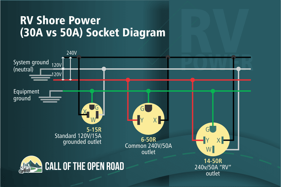
- Receptacle Type: RV power inlets typically come in two standard configurations: 30-amp and 50-amp. The appropriate choice depends on the RV’s electrical system and power requirements.
- Connector Configuration: The power inlet receptacle features a specific configuration of prongs and a grounding terminal to match the corresponding plug on the power pedestal.
- Electrical Ratings: Power inlets are rated for specific amperage and voltage, which must align with the RV’s electrical system and the power source.
- Safety Features: Modern power inlets incorporate safety features such as weather-resistant construction, surge protection, and ground fault circuit interrupters (GFCIs) to enhance electrical safety.
Proper selection, installation, and maintenance of the power inlet are critical for the safe and efficient operation of an RV’s electrical system. By understanding the various facets of power inlets, as outlined above, RV owners and technicians can ensure a reliable connection to external power sources, minimizing electrical hazards and maximizing the enjoyment of RV living.
Circuit Breaker
Within the context of RV pedestal wiring diagrams, circuit breakers play a pivotal role in ensuring the safety and reliability of the electrical system. These devices act as guardians of the electrical infrastructure, safeguarding against potential hazards and preventing catastrophic failures.
- Overcurrent Protection: Circuit breakers are designed to interrupt the flow of excessive current, which can occur during overloads or short circuits. This prevents overheating, electrical fires, and damage to appliances and wiring.
- Resettable Mechanism: Unlike fuses, which blow and require replacement, circuit breakers can be manually reset after tripping, restoring power once the fault has been resolved.
- Amperage Rating: Each circuit breaker has a specific amperage rating, indicating the maximum current it can safely handle. Choosing the correct amperage rating is crucial to ensure proper protection.
- Location and Accessibility: Circuit breakers are typically located in the RV’s electrical panel or pedestal, making them easily accessible for inspection and resetting.
Understanding the function and importance of circuit breakers in RV pedestal wiring diagrams is paramount for maintaining a safe and reliable electrical system. These devices serve as the first line of defense against electrical hazards, protecting RV owners and their investments from harm.
Wiring
In the context of RV pedestal wiring diagrams, wiring plays a critical role in the safe and efficient distribution of electrical power throughout the recreational vehicle. These electrical conductors serve as the pathways for electricity to flow from the power inlet to the RV’s electrical panel and various appliances.
The importance of wiring within RV pedestal wiring diagrams cannot be overstated. Without properly installed and maintained wiring, electrical power would not reach the RV’s essential components, rendering them inoperable. The diagram provides a visual representation of the wiring layout, including the size, type, and routing of electrical conductors.
Real-life examples of wiring within RV pedestal wiring diagrams include:
- The thick black wire that carries 120-volt power from the power inlet to the RV’s electrical panel.
- The red, black, and white wires that connect the electrical panel to the RV’s air conditioner.
- The green wire that provides a grounding path for the RV’s electrical system.
Understanding the wiring component of RV pedestal wiring diagrams is essential for several practical reasons:
- Troubleshooting electrical faults: The diagram helps identify the specific wires involved in a circuit, making it easier to locate and repair faults.
- Adding or modifying electrical circuits: The diagram provides a roadmap for safely adding new circuits or modifying existing ones.
- Ensuring electrical safety: By following the diagram, electricians and RV owners can verify that the wiring meets electrical codes and standards, minimizing the risk of electrical fires and shocks.
In summary, wiring is a critical component of RV pedestal wiring diagrams, enabling the safe and efficient distribution of electrical power throughout the recreational vehicle. Understanding the wiring layout is essential for troubleshooting, modifications, and ensuring electrical safety, empowering RV owners and technicians to maintain and enjoy their vehicles with confidence.
Grounding
Within the context of RV pedestal wiring diagrams, grounding holds paramount importance as a safety measure that safeguards individuals and the electrical system from harm. By establishing a conductive path between the RV’s electrical system and the earth, grounding ensures that any stray electrical currents are safely dissipated, preventingand electrical fires.
- Electrical Safety: Grounding provides a low-resistance path for electrical current to flow in the event of a fault, diverting it away from the RV’s metal components and appliances. This prevents the buildup of dangerous voltages that could otherwise pose a shock hazard.
- Protecting Appliances: Grounding helps protect appliances and electronic devices by preventing power surges and fluctuations from damaging their sensitive circuitry. By providing a stable reference point for electrical potential, grounding ensures that appliances operate safely and efficiently.
- Compliance with Codes: Most electrical codes require RV pedestal wiring diagrams to incorporate proper grounding. This ensures that RV electrical systems meet safety standards and minimize the risk of electrical accidents.
- Real-life Example: The green wire in an RV pedestal wiring diagram typically represents the grounding conductor. It connects the RV’s electrical panel to a grounding rod driven into the earth, providing a direct path for electrical current to flow into the ground.
Understanding the significance of grounding in RV pedestal wiring diagrams empowers RV owners and technicians to prioritize electrical safety and ensure the reliable operation of their recreational vehicles. By adhering to proper grounding practices, individuals can minimize the risks associated with electrical faults, safeguarding both themselves and their investments.
Color Coding
Within the context of RV pedestal wiring diagrams, color coding plays a vital role in simplifying troubleshooting, repairs, and maintenance. By assigning specific colors to different types of electrical circuits, these diagrams provide a visual cue that helps electricians and RV owners quickly identify and trace wires, even in complex electrical systems.
Color coding is a critical component of RV pedestal wiring diagrams because it enables efficient troubleshooting. When an electrical fault occurs, electricians can use the diagram to quickly identify the affected circuit by its color-coded wire. This allows them to isolate the problem and focus their efforts on repairing the specific circuit, saving time and effort.
Real-life examples of color coding within RV pedestal wiring diagrams include:
- Black wires are typically used for live wires, which carry electricity from the power source to electrical devices.
- White wires are used for neutral wires, which provide a return path for electrical current.
- Green or bare copper wires are used for grounding wires, which protect against electrical shocks by providing a path for stray electrical current to flow into the ground.
- Red wires are often used for high-voltage circuits, such as those that power air conditioners or electric stoves.
Understanding the color coding system used in RV pedestal wiring diagrams is essential for anyone who works on or maintains RV electrical systems. By following the color-coded wires, electricians can quickly and safely troubleshoot, repair, and modify electrical circuits, ensuring the safety and reliability of the RV’s electrical system.
In summary, color coding is a crucial element of RV pedestal wiring diagrams, providing a visual representation of the electrical system that simplifies troubleshooting, repairs, and maintenance. By adhering to standardized color-coding practices, RV owners and technicians can ensure the safe and efficient operation of their recreational vehicles.
Wire Gauge
Within the context of RV pedestal wiring diagrams, wire gauge plays a pivotal role in ensuring the safe and efficient operation of the electrical system. The thickness of electrical wires directly influences their ability to carry current without overheating or causing voltage drop, making it a critical factor in the design and installation of RV electrical systems.
- Electrical Resistance: Wire gauge is inversely proportional to electrical resistance, meaning thicker wires have lower resistance. Lower resistance allows for better current flow, reducing voltage drop and ensuring that electrical devices receive the power they need.
- Amperage Capacity: The amperage capacity of a wire is determined by its gauge. Thicker wires can safely carry higher amperage without overheating, while thinner wires are limited in the amount of current they can handle.
- Voltage Drop: As current flows through a wire, some voltage is lost due to resistance. Thicker wires experience less voltage drop over a given distance compared to thinner wires, ensuring that electrical devices receive the appropriate voltage.
- Real-life Example: In an RV pedestal wiring diagram, the power inlet wire is typically thicker than the wires that connect to individual appliances. This is because the power inlet wire carries the highest amperage and must be able to handle the electrical load of the entire RV.
Understanding the relationship between wire gauge and current-carrying capacity is essential for ensuring the safety and reliability of RV electrical systems. By selecting the appropriate wire gauge for each circuit, RV owners and technicians can minimize voltage drop, prevent overheating, and ensure that electrical devices operate as intended.
Electrical Standards
In the context of RV pedestal wiring diagrams, compliance with electrical standards is paramount for ensuring the safety, reliability, and longevity of the electrical system. Adherence to industry-recognized codes, such as the National Electrical Code (NEC), provides a comprehensive framework for the design, installation, and maintenance of RV electrical systems.
- Safe Electrical Practices: Electrical standards establish guidelines for the proper installation and use of electrical components, minimizing the risk of electrical fires, shocks, and other hazards.
- Component Compatibility: Standards ensure that electrical components, such as circuit breakers, wiring, and outlets, are compatible with each other and meet specific safety requirements.
- Real-life Example: The NEC specifies the appropriate wire gauge for different amperage loads, ensuring that wires can safely carry the electrical current without overheating.
- Inspection and Approval: Compliance with electrical standards often requires inspections by qualified electricians to verify the safety and code compliance of RV electrical systems.
By adhering to electrical standards in RV pedestal wiring diagrams, RV owners and technicians can ensure that their electrical systems operate safely and efficiently, minimizing the risk of electrical malfunctions and protecting themselves and their investments.
RV Amperage
In the context of RV pedestal wiring diagrams, RV amperage plays a critical role in determining the size and capacity of the pedestal wiring. The amperage rating of an RV indicates the maximum amount of electrical current it can draw from an external power source.
The pedestal wiring must be able to safely handle the electrical load of the RV without overheating or causing voltage drop. If the pedestal wiring is not properly sized for the RV’s amperage, it can pose a safety hazard and damage electrical components.
For example, a 30-amp RV will require a pedestal wiring diagram that specifies 30-amp wiring throughout the system. This includes the power inlet, circuit breakers, and all of the wires that connect to the RV’s electrical panel and appliances.
Understanding the relationship between RV amperage and pedestal wiring is essential for ensuring the safe and reliable operation of an RV electrical system. By following the specifications outlined in the pedestal wiring diagram, RV owners can ensure that their RV’s electrical system is properly configured to handle the electrical load.
Electrical Safety
In an RV pedestal wiring diagram, electrical safety is paramount. Proper installation and maintenance of the pedestal wiring are crucial for preventing electrical fires and other hazards that could endanger the occupants of the RV and damage the electrical system.
Electrical fires can occur due to various factors, including loose connections, faulty wiring, and overloads. A well-designed pedestal wiring diagram ensures that all electrical components are properly connected and protected, minimizing the risk of electrical fires.
For example, the pedestal wiring diagram specifies the appropriate wire gauge for each circuit, ensuring that the wires can safely carry the electrical current without overheating. It also indicates the correct type of circuit breakers to use, which trip to interrupt the flow of electricity in the event of a fault.
Understanding the importance of electrical safety in RV pedestal wiring diagrams empowers RV owners and technicians to take the necessary precautions to prevent electrical hazards. By following the guidelines outlined in the diagram and adhering to proper electrical practices, they can ensure the safe and reliable operation of their RV’s electrical system.
Regular inspection and maintenance of the pedestal wiring are also essential for electrical safety. Loose connections, damaged wires, and corrosion can compromise the integrity of the electrical system and increase the risk of electrical hazards. Periodic inspections and prompt repairs can help prevent these issues and ensure the continued safe operation of the RV’s electrical system.
Troubleshooting
Within the context of RV pedestal wiring diagrams, troubleshooting electrical problems is a critical aspect that highlights the diagram’s practical value. These diagrams serve as essential tools for diagnosing and resolving electrical issues, ensuring the safety and reliable operation of the RV’s electrical system.
Pedestal wiring diagrams provide a visual representation of the electrical connections within the RV, enabling technicians and RV owners to trace circuits, identify faulty components, and determine the root cause of electrical problems. Without a proper diagram, troubleshooting electrical issues can be a time-consuming and challenging task, often requiring extensive trial-and-error methods.
For example, if an RV’s air conditioner is not working, the pedestal wiring diagram can guide the technician to the circuit breaker that controls the air conditioner. By checking the circuit breaker and its associated wiring, the technician can determine if the problem is a tripped circuit breaker, a faulty wire, or an issue with the air conditioner itself.
Understanding the connection between troubleshooting and RV pedestal wiring diagrams empowers RV owners and technicians to approach electrical problems with a systematic and informed approach. By utilizing the diagram as a roadmap, they can efficiently identify and resolve electrical issues, ensuring the safe and reliable operation of their RV’s electrical system.


Related Posts


