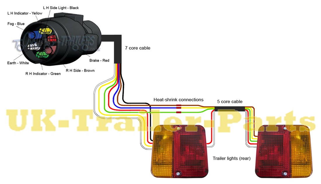
A wiring diagram of trailer lights outlines the electrical connections between a trailer and the towing vehicle, ensuring proper functioning of the lights for safety and compliance. For instance, the seven-pin connector commonly used in RV trailers includes wires for tail lights, turn signals, brake lights, ground, and auxiliary power.
These diagrams are crucial for troubleshooting issues, adding new lights, or modifying existing electrical systems. They improve safety by ensuring that lights are visible to other drivers, reducing the risk of accidents. Historically, the development of standardized wiring configurations has simplified the installation and maintenance of trailer lights.
This article will delve deeper into the components, connections, and best practices involved in wiring trailer lights, providing valuable insights for safe and effective trailer operation.
Understanding the essential aspects of “Wiring Diagram Of Trailer Lights” is crucial for ensuring the safety and functionality of trailer lighting systems. These diagrams serve as blueprints for the electrical connections between trailers and towing vehicles, guiding proper installation, troubleshooting, and maintenance.
- Components: Wires, connectors, lights, fuses
- Connections: Color-coded wires, pin configurations
- Types: 4-pin, 5-pin, 7-pin connectors
- Functions: Tail lights, brake lights, turn signals
- Safety: Ensures visibility, prevents accidents
- Regulations: Compliance with DOT standards
- Troubleshooting: Locating electrical faults
- Modifications: Adding new lights or accessories
- Maintenance: Inspecting wires, cleaning connectors
- Customization: Tailoring to specific trailer needs
These aspects are interconnected and play vital roles in the effectiveness and reliability of trailer lighting systems. Proper wiring ensures that lights are visible to other drivers, enhancing safety on the road. Compliance with regulations prevents legal issues and promotes responsible trailer operation. Understanding these aspects empowers individuals to troubleshoot problems, customize systems, and maintain trailer lights for optimal performance.
Components
In the context of “Wiring Diagram Of Trailer Lights,” understanding the individual components and their connections is essential. Wires, connectors, lights, and fuses play critical roles in ensuring the proper functioning and safety of trailer lighting systems.
Wires serve as the pathways for electrical current, transmitting power from the towing vehicle to the trailer lights. Connectors establish secure electrical connections between different components, ensuring a reliable flow of electricity. Lights, including tail lights, brake lights, and turn signals, are the visible indicators that communicate the trailer’s presence and intentions to other drivers. Fuses act as safety devices, protecting the electrical system from damage caused by excessive current.
The wiring diagram provides a comprehensive overview of how these components are interconnected and function together. It guides the proper installation, maintenance, and troubleshooting of trailer lighting systems. For instance, the diagram specifies the appropriate wire gauge for different electrical loads, ensuring that wires can safely carry the required current without overheating. It also indicates the correct pin configuration for connectors, preventing misconnections and ensuring proper signal transmission. By understanding these connections, individuals can effectively diagnose and resolve electrical issues, ensuring the safety and reliability of their trailer lighting systems.
In summary, the components of “Wires, connectors, lights, fuses” form the backbone of “Wiring Diagram Of Trailer Lights.” Proper understanding and application of these components are crucial for the effective functioning of trailer lighting systems, promoting safety on the road and ensuring compliance with regulations.
Connections
In the realm of “Wiring Diagram Of Trailer Lights,” the connections between color-coded wires and pin configurations hold immense significance. These carefully orchestrated connections are the backbone of trailer lighting systems, ensuring proper functionality, safety, and compliance with regulations.
Color-coded wires serve as a universal language in electrical systems, simplifying the identification and connection of different components. The wiring diagram specifies the color code for each wire, indicating its function and the corresponding pin configuration in the connectors. This standardization allows for quick and accurate installation, reducing the risk of errors that could compromise the lighting system.
Pin configurations, often standardized to industry norms, define the specific arrangement of terminals within connectors. By adhering to these configurations, the diagram ensures that wires are connected to the correct terminals, preventing short circuits, malfunctions, and potential hazards. Real-life examples abound, such as the 7-pin connector commonly used in RV trailers, where each pin is designated for a specific function: tail lights, brake lights, turn signals, ground, and auxiliary power.
Understanding these connections empowers individuals to troubleshoot problems, customize systems, and maintain trailer lights for optimal performance. By following the wiring diagram and adhering to the color-coded wires and pin configurations, DIY enthusiasts and professionals alike can confidently work on trailer lighting systems, ensuring safety and reliability.
Types
Within the realm of “Wiring Diagram Of Trailer Lights,” the “Types: 4-pin, 5-pin, 7-pin connectors” play a crucial role in establishing electrical connections between towing vehicles and trailers. These connectors come in various configurations, each tailored to specific lighting requirements and industry standards.
- Pin Configuration: 4-pin connectors feature four terminals, typically used for basic lighting functions such as tail lights and brake lights. 5-pin connectors add a dedicated ground wire, enhancing safety and reducing the risk of electrical issues. 7-pin connectors are commonly found in RV trailers, providing connections for tail lights, brake lights, turn signals, ground, and auxiliary power.
- Wiring Compatibility: Each connector type requires specific wire gauges and color-coding to ensure proper functionality. The wiring diagram specifies the appropriate wire sizes and colors for each pin, ensuring compatibility between the towing vehicle and trailer.
- Industry Standards: 4-pin and 7-pin connectors adhere to industry-established standards, such as those set by the Society of Automotive Engineers (SAE). These standards ensure universal compatibility across different manufacturers, simplifying installation and maintenance.
- Trailer Compatibility: The choice of connector type depends on the specific lighting requirements of the trailer. Heavier trailers with more lighting functions typically require 7-pin connectors to accommodate the additional electrical needs.
Understanding the different types of connectors and their implications is essential for proper installation, troubleshooting, and maintenance of trailer lighting systems. By adhering to the wiring diagram and selecting the appropriate connector type, individuals can ensure the safe and reliable operation of their trailer lights.
Functions
Within the realm of “Wiring Diagram Of Trailer Lights,” the “Functions: Tail lights, brake lights, turn signals” hold paramount importance, ensuring the safe and effective communication of a trailer’s presence, intentions, and braking status on the road.
- Tail Lights: As the rearmost lights on a trailer, tail lights serve as constant indicators of the trailer’s presence, especially during nighttime or low-visibility conditions. They enhance visibility and help prevent rear-end collisions.
- Brake Lights: Activated when the trailer’s brakes are applied, brake lights emit a brighter, more intense red light to alert following drivers of the trailer’s deceleration. Prompt and clear brake light signals are critical in preventing accidents.
- Turn Signals: Turn signals, often amber in color, indicate the trailer’s intended direction of travel. They play a crucial role in safe lane changes, turns, and overtaking maneuvers, informing other drivers of the trailer’s upcoming movements.
These functions are integral to the safe operation of trailers, and the wiring diagram provides a detailed blueprint for connecting these lights to the towing vehicle’s electrical system. Proper wiring ensures that each light functions as intended, enabling clear and timely communication of the trailer’s status to other road users. By understanding these functions and their implications, individuals can effectively troubleshoot and maintain trailer lighting systems, contributing to overall road safety.
Safety
Within the realm of “Wiring Diagram Of Trailer Lights,” the aspect of “Safety: Ensures visibility, prevents accidents” takes center stage. A properly wired lighting system is not merely a convenience but a critical safety feature that enhances the visibility of trailers on the road, reducing the risk of accidents and safeguarding lives.
- Clear Visibility: Properly functioning trailer lights ensure that the trailer’s presence is clearly visible to other drivers, especially during nighttime or in low-visibility conditions. This enhanced visibility significantly reduces the likelihood of rear-end collisions, as following vehicles have ample time to react and adjust their driving accordingly.
- Brake Light Signals: When a trailer’s brakes are applied, the brake lights emit a brighter, more intense red light to alert following drivers of the trailer’s deceleration. Prompt and clear brake light signals are essential in preventing rear-end collisions, as they provide other drivers with crucial information about the trailer’s upcoming maneuvers.
- Turn Signal Indications: Turn signals, often amber in color, indicate the trailer’s intended direction of travel. These signals play a vital role in safe lane changes, turns, and overtaking maneuvers, informing other drivers of the trailer’s upcoming movements and reducing the risk of accidents due to miscommunication or confusion.
- Compliance with Regulations: In many regions, properly wired trailer lights are a legal requirement for road safety. Adhering to these regulations not only ensures compliance but also contributes to the overall safety of all road users by promoting visibility and preventing accidents.
In essence, a comprehensive understanding of “Wiring Diagram Of Trailer Lights” empowers individuals to maintain and troubleshoot their trailer lighting systems effectively. By ensuring the proper functioning of tail lights, brake lights, and turn signals, they actively contribute to road safety, preventing accidents and safeguarding lives.
Regulations
Within the realm of “Wiring Diagram Of Trailer Lights,” “Regulations: Compliance with DOT standards” holds significant importance, ensuring that trailer lighting systems adhere to established safety guidelines and legal requirements. The U.S. Department of Transportation (DOT) has set forth specific regulations for trailer lighting, aimed at enhancing visibility, promoting road safety, and preventing accidents.
Compliance with DOT standards is a critical component of “Wiring Diagram Of Trailer Lights” as it provides a framework for the proper installation, maintenance, and operation of trailer lighting systems. The wiring diagram serves as a blueprint for ensuring that lights are positioned, wired, and connected according to DOT specifications. This includes guidelines for wire gauge, color-coding, connector types, and light placement, all of which contribute to the effectiveness and safety of the lighting system.
Real-life examples of DOT regulations within “Wiring Diagram Of Trailer Lights” include:
- Tail Light Visibility: DOT regulations specify the minimum visibility requirements for tail lights, ensuring that they are visible from a specific distance at night.
- Brake Light Intensity: Brake lights must meet certain intensity standards to provide clear and timely signals to following drivers.
- Turn Signal Placement: DOT regulations dictate the placement of turn signals to ensure they are visible from specific angles and distances.
Understanding the connection between “Regulations: Compliance with DOT standards” and “Wiring Diagram Of Trailer Lights” has practical applications in various settings. For instance, manufacturers utilize these standards to design and produce trailers with lighting systems that meet DOT requirements. Similarly, professional installers and DIY enthusiasts rely on wiring diagrams to ensure their installations comply with DOT regulations, promoting safety on the roads.
In summary, “Regulations: Compliance with DOT standards” plays a crucial role in “Wiring Diagram Of Trailer Lights” by providing a framework for safe and compliant trailer lighting systems. Adhering to DOT regulations ensures that trailers are clearly visible, promoting road safety, preventing accidents, and fostering a culture of responsible trailering practices.
Troubleshooting
In the intricate realm of “Wiring Diagram Of Trailer Lights,” “Troubleshooting: Locating electrical faults” emerges as a critical component, akin to a diagnostic tool that empowers individuals to identify and resolve issues within their trailer’s lighting system. A thorough understanding of electrical faults and their relationship with wiring diagrams is essential for ensuring the proper functioning, safety, and longevity of trailer lighting systems.
Wiring diagrams provide a comprehensive blueprint of the electrical connections within a trailer lighting system. When a fault occurs, whether due to loose connections, damaged wires, or faulty components, the wiring diagram serves as a guide for systematic troubleshooting, allowing individuals to trace the electrical pathways and pinpoint the source of the problem. Real-life examples abound, such as a dim turn signal that could indicate a faulty bulb or a loose connection in the wiring harness. By referencing the wiring diagram, one can identify the specific circuit and component associated with the turn signal, enabling targeted troubleshooting and repair.
The practical applications of understanding the connection between “Troubleshooting: Locating electrical faults” and “Wiring Diagram Of Trailer Lights” extend beyond basic repairs. For instance, when modifying or adding new lighting fixtures to a trailer, the wiring diagram becomes indispensable for ensuring proper integration into the existing electrical system. It provides insights into the electrical load capacity of each circuit, preventing overloading and potential hazards. Moreover, in situations where a trailer experiences intermittent electrical issues, the wiring diagram empowers individuals to conduct thorough and methodical troubleshooting, eliminating guesswork and ensuring a swift resolution.
In summary, “Troubleshooting: Locating electrical faults” and “Wiring Diagram Of Trailer Lights” are inextricably linked, forming a powerful combination for maintaining safe and reliable trailer lighting systems. By leveraging wiring diagrams for troubleshooting, individuals gain the ability to diagnose and resolve electrical faults effectively, ensuring the proper functioning of their trailer lights, enhancing visibility on the road, and contributing to overall safety.
Modifications
Within the realm of “Wiring Diagram Of Trailer Lights,” “Modifications: Adding new lights or accessories” emerges as a critical component, akin to an artist’s palette that expands the creative possibilities and functionalities of a trailer lighting system. This connection stems from the fact that any addition or alteration to a trailer’s lighting setup necessitates a corresponding update to the wiring diagram, ensuring compatibility, safety, and optimal performance.
Real-life examples of “Modifications: Adding new lights or accessories” within “Wiring Diagram Of Trailer Lights” abound. Consider the addition of auxiliary lighting, such as off-road lights or work lights, to enhance visibility in challenging conditions. These additions require careful integration into the existing wiring system, and the wiring diagram serves as a guide for determining appropriate wire gauge, circuit capacity, and connection points. Moreover, the advent of LED lighting technology has opened up new possibilities for customization and energy efficiency, and the wiring diagram plays a crucial role in ensuring proper installation and compatibility with the trailer’s electrical system.
The practical significance of understanding the connection between “Modifications: Adding new lights or accessories” and “Wiring Diagram Of Trailer Lights” extends beyond basic installations. For instance, when troubleshooting electrical issues related to newly added lights or accessories, the wiring diagram becomes an invaluable tool for tracing circuits, identifying potential faults, and implementing effective repairs. Furthermore, as trailers are often used for specialized purposes, such as hauling equipment or transporting livestock, the ability to modify the lighting system to meet specific needs is essential. The wiring diagram empowers individuals to make informed decisions regarding the placement, wiring, and integration of new lights or accessories, ensuring a safe and tailored lighting setup.
In summary, “Modifications: Adding new lights or accessories” and “Wiring Diagram Of Trailer Lights” are inextricably linked, forming a symbiotic relationship that enables customization, functionality, and safety. By understanding this connection, individuals gain the ability to modify their trailer lighting systems with confidence, ensuring optimal performance, compliance with regulations, and a tailored lighting setup that meets their specific needs.
Maintenance
Within the realm of “Wiring Diagram Of Trailer Lights,” “Maintenance: Inspecting wires, cleaning connectors” emerges as a critical component, akin to a vigilant guardian that ensures the safe and reliable operation of a trailer’s lighting system. This connection stems from the fact that electrical faults and malfunctions often arise from neglected or poorly maintained wires and connectors, emphasizing the crucial role of regular inspections and maintenance.
Real-life examples of “Maintenance: Inspecting wires, cleaning connectors” within “Wiring Diagram Of Trailer Lights” abound. Consider the consequences of loose or corroded wire connections, which can lead to intermittent lighting issues, flickering lights, or even complete electrical failure. Regular inspection and cleaning of these connections can effectively prevent such problems, ensuring a stable and reliable electrical system. Another common issue is damaged or frayed wires, which can result from exposure to harsh weather conditions or physical wear and tear. By visually inspecting the wires and replacing any damaged sections, individuals can proactively address potential hazards and maintain the integrity of the lighting system.
The practical applications of understanding the connection between “Maintenance: Inspecting wires, cleaning connectors” and “Wiring Diagram Of Trailer Lights” extend beyond basic troubleshooting. For instance, when modifying or adding new lights or accessories to a trailer, it is essential to ensure that the existing wiring and connectors are in good condition to handle the additional electrical load. By referencing the wiring diagram and conducting thorough inspections, individuals can make informed decisions regarding the suitability of the wiring system and implement necessary upgrades or modifications to ensure safety and optimal performance.
In summary, “Maintenance: Inspecting wires, cleaning connectors” and “Wiring Diagram Of Trailer Lights” are inextricably linked, forming a symbiotic relationship that promotes the longevity, reliability, and safety of trailer lighting systems. By understanding this connection, individuals gain the ability to maintain their trailers proactively, preventing electrical issues, ensuring compliance with regulations, and fostering a culture of responsible trailering practices.
Customization
Within the realm of “Wiring Diagram Of Trailer Lights,” “Customization: Tailoring to specific trailer needs” emerges as a critical component, akin to a skilled craftsman adapting a lighting system to meet unique requirements. This customization encompasses a wide range of considerations, from the selection of components to the integration of accessories, all guided by the overarching wiring diagram.
- Component Selection: The wiring diagram serves as a blueprint for selecting appropriate electrical components, such as lights, connectors, and wiring harnesses, ensuring compatibility and optimal performance.
- Accessory Integration: Trailers often require additional lighting accessories, such as auxiliary lights, work lights, or even solar panels. The wiring diagram guides the integration of these accessories, ensuring proper wiring, load balancing, and compliance with regulations.
- Custom Layouts: The wiring diagram empowers individuals to design custom lighting layouts that cater to specific trailer configurations or specialized applications, such as hauling equipment or transporting livestock.
- Electrical Modifications: The wiring diagram provides a framework for implementing electrical modifications, such as upgrading lighting systems to LED technology or installing additional circuits to support specialized equipment.
In summary, “Customization: Tailoring to specific trailer needs” and “Wiring Diagram Of Trailer Lights” are inextricably linked, forming a symbiotic relationship that empowers individuals to adapt their trailer lighting systems to meet unique requirements. By understanding this connection, individuals gain the ability to create tailored lighting solutions that enhance functionality, safety, and compliance with regulations.


Related Posts


