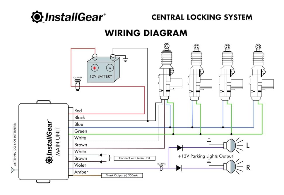
A “Power Door Lock Wiring Diagram” outlines the electrical connections and components necessary to operate a vehicle’s power door lock system. It provides a visual representation of the wiring harness, switches, actuators, and other elements involved in enabling and disabling the locks.
This diagram is crucial for understanding the system’s functionality, troubleshooting electrical issues, and performing repairs or modifications. It ensures the proper installation and operation of the power door lock system, enhancing convenience and security for vehicle occupants.
Historically, the development of power door lock systems has evolved alongside advances in automotive electronics. Early systems relied on mechanical linkages, but the introduction of electronic control units (ECUs) and actuators enabled more sophisticated and reliable systems.
A Power Door Lock Wiring Diagram outlines the essential aspects of a vehicle’s power door lock system. Understanding these aspects is crucial for troubleshooting, repairs, and modifications.
- Components: Relays, switches, actuators, wiring harness, control module
- Circuitry: Power distribution, signal transmission, grounding
- Installation: Wire routing, connector types, mounting locations
- Troubleshooting: Identifying electrical faults, testing components
- Security: Anti-theft features, remote access control
- Customization: Adding keyless entry, remote start
- Compatibility: Integration with vehicle’s electrical system
- Diagnostics: Using diagnostic tools to analyze system issues
- Maintenance: Inspecting connections, cleaning components
- Safety: Ensuring proper operation for occupant protection
These aspects provide a comprehensive understanding of Power Door Lock Wiring Diagrams, enabling technicians and enthusiasts to effectively manage the system’s functionality and enhance the convenience and security of vehicles.
Components
Within the context of Power Door Lock Wiring Diagrams, understanding the individual components plays a vital role in comprehending the system’s functionality and addressing any issues that may arise. These components, including relays, switches, actuators, wiring harness, and control module, work in conjunction to enable the seamless operation of the power door lock system.
- Relays: Electromagnetic switches that amplify low-power signals to control higher-power circuits, such as those used to activate door lock actuators.
- Switches: Devices that control the flow of electrical current, such as the door lock switches located on the vehicle’s doors or key fob.
- Actuators: Electric motors that convert electrical signals into mechanical motion, used to physically lock and unlock the vehicle’s doors.
- Wiring harness: A bundle of wires that connects the various components of the power door lock system, providing the necessary electrical pathways for signals and power.
- Control module: An electronic device that serves as the central brain of the power door lock system, receiving inputs from switches and sensors, and controlling the operation of relays and actuators.
By understanding the roles and interconnections of these components, technicians and enthusiasts can effectively troubleshoot, repair, and modify power door lock systems, ensuring their proper functionality and enhancing the convenience and security of vehicles.
Circuitry
Within the context of Power Door Lock Wiring Diagrams, the circuitry responsible for power distribution, signal transmission, and grounding plays a pivotal role in ensuring the system’s functionality and reliability. These elements work in tandem to provide the necessary electrical infrastructure for the system to operate effectively.
Power distribution involves the proper delivery of electrical power from the vehicle’s battery to the various components of the power door lock system, such as actuators, switches, and the control module. This ensures that these components have the necessary voltage and current to operate as intended.
Signal transmission involves the transfer of electrical signals between different components of the system. These signals carry commands and data that control the locking and unlocking of the vehicle’s doors. The accuracy and reliability of signal transmission are crucial for the proper operation of the system.
Grounding provides a common reference point for electrical circuits, ensuring that excess electrical current can safely dissipate. This helps protect the system’s components from damage caused by electrical surges or short circuits.
Understanding the principles of circuitry in the context of Power Door Lock Wiring Diagrams enables technicians and enthusiasts to troubleshoot and repair electrical faults effectively. By ensuring that power distribution, signal transmission, and grounding are properly implemented and maintained, the power door lock system can operate reliably and securely, enhancing the convenience and safety of the vehicle’s occupants.
Installation
In the context of Power Door Lock Wiring Diagrams, installation practices play a critical role in ensuring the system’s reliability and functionality. Proper wire routing, selection of appropriate connector types, and careful consideration of mounting locations are essential aspects of a successful installation.
Wire routing involves determining the paths that wires will take throughout the vehicle. Careful planning is necessary to avoid interference with other components, ensure protection from heat and moisture, and facilitate future maintenance or troubleshooting. Connector types must be chosen to match the specific requirements of the system, considering factors such as current carrying capacity, environmental conditions, and ease of connection and disconnection.
Mounting locations for components such as actuators and control modules must be chosen to provide secure and stable support while allowing for proper heat dissipation and accessibility for maintenance. Failure to adhere to proper installation practices can lead to electrical faults, system malfunctions, and potential safety hazards.
Understanding the cause-and-effect relationship between installation practices and the performance of a Power Door Lock Wiring Diagram is crucial for technicians and installers. By following recommended guidelines and industry best practices, installers can ensure that the system operates reliably and safely, providing enhanced convenience and security for vehicle occupants.
Troubleshooting
Within the context of Power Door Lock Wiring Diagrams, troubleshooting plays a critical role in maintaining the system’s functionality and reliability. By identifying electrical faults and testing components, technicians can quickly pinpoint issues and implement effective repairs.
Power Door Lock Wiring Diagrams provide a visual representation of the system’s electrical connections, enabling technicians to trace circuits, locate components, and identify potential problem areas. This detailed schematic serves as a valuable tool for troubleshooting, allowing technicians to methodically eliminate possible causes and isolate the source of the fault.
Testing components involves using specialized tools and techniques to assess their functionality. This may include measuring voltage and current, checking for continuity, or activating components to observe their response. By comparing the test results to known specifications, technicians can determine whether a component is faulty and requires replacement.
The ability to effectively troubleshoot Power Door Lock Wiring Diagrams is essential for ensuring the proper operation of the system. By identifying electrical faults and testing components, technicians can restore the system to its intended functionality, enhancing the convenience and security of the vehicle.
Security
In the context of Power Door Lock Wiring Diagrams, security is a paramount consideration, encompassing anti-theft features and remote access control mechanisms. These elements work in conjunction to protect vehicles from unauthorized entry and provide convenient access for authorized users.
- Anti-lockout feature: Ensures that occupants are not accidentally locked out of their vehicle. When activated, this feature allows for re-entry even if the keys are locked inside.
- Remote keyless entry: Enables users to lock and unlock their vehicles using a key fob or smartphone app, providing convenience and eliminating the need for physical keys.
- Anti-theft alarm: Triggers an alarm when unauthorized entry is attempted, deterring theft and alerting the vehicle owner and surrounding individuals.
- Immobilizer system: Prevents the engine from starting without the correct key or transponder, adding an extra layer of protection against vehicle theft.
These security measures are intricately connected to the Power Door Lock Wiring Diagram, as they rely on the electrical connections and components outlined in the diagram to function effectively. Understanding the interrelationships between these elements is essential for technicians and enthusiasts seeking to enhance the security of their vehicles.
Customization
In the context of Power Door Lock Wiring Diagrams, customization plays a significant role in enhancing convenience and functionality for vehicle owners. Adding keyless entry and remote start features involves modifying the wiring diagram to incorporate additional components and connections.
Keyless entry systems allow users to unlock and lock their vehicles without using a physical key. This is achieved by integrating a key fob or smartphone app with the vehicle’s electrical system. The wiring diagram must be modified to include the necessary connections for the key fob receiver, door lock actuators, and control module.
Remote start systems enable users to start their vehicles remotely, typically using a key fob or smartphone app. This requires the addition of a remote start module and associated wiring to the system. The wiring diagram must be updated to include these components and the connections to the ignition system, starter solenoid, and other relevant components.
Understanding the cause-and-effect relationship between customization and Power Door Lock Wiring Diagrams is crucial for technicians and enthusiasts seeking to modify their vehicles’ door lock systems. By carefully modifying the wiring diagram and incorporating the necessary components, they can enhance the convenience and functionality of their vehicles.
Compatibility
In the context of Power Door Lock Wiring Diagrams, compatibility plays a crucial role in ensuring seamless integration with the vehicle’s electrical system. Various aspects or components must be considered to achieve proper functionality and avoid potential issues.
- Electrical Load: The power door lock system must be compatible with the vehicle’s electrical system’s load capacity. Adding additional components, such as remote start or keyless entry, may increase the electrical load, requiring upgrades to the alternator or battery.
- CAN Bus Compatibility: Many modern vehicles utilize a Controller Area Network (CAN Bus) for communication between electronic modules. The power door lock system must be compatible with the vehicle’s CAN Bus to exchange signals and commands effectively.
- Security Features: The power door lock system should be compatible with the vehicle’s security features, such as anti-theft alarms and immobilizers. Integrating the system with existing security measures ensures a cohesive and comprehensive security solution.
- Diagnostic Capabilities: The power door lock system should be compatible with the vehicle’s diagnostic tools and software. This allows technicians to troubleshoot and identify any issues within the system efficiently.
Understanding and addressing these compatibility aspects are crucial when designing, installing, or modifying Power Door Lock Wiring Diagrams. By ensuring proper integration with the vehicle’s electrical system, technicians and enthusiasts can enhance the functionality, reliability, and security of their vehicle’s power door lock system.
Diagnostics
Diagnostics plays a critical role in maintaining a fully functional power door lock system. Specialized tools and techniques are employed to identify underlying issues, ensuring the system operates as intended.
- Fault Code Retrieval: Diagnostic tools can retrieve fault codes stored in the system’s control module. These codes provide valuable insights into potential issues, guiding technicians towards the root cause.
- Circuit Testing: Specialized tools can measure voltage, current, and resistance within the wiring harness, identifying open circuits, short circuits, or excessive resistance that may hinder proper system operation.
- Actuator Testing: Diagnostic tools can activate and test door lock actuators, assessing their functionality and response to commands from the control module.
- Switch Testing: Diagnostic tools can verify the functionality of door lock switches, ensuring they send the appropriate signals to the control module when actuated.
By utilizing diagnostic tools to analyze system issues within the context of Power Door Lock Wiring Diagrams, technicians can effectively troubleshoot and repair faults, restoring the system to optimal performance. This ensures the convenience and security features of the power door lock system are maintained, contributing to a positive user experience.
Maintenance
Within the context of Power Door Lock Wiring Diagrams, maintenance plays a crucial role in ensuring the system’s longevity and reliability. Regular inspection of connections and cleaning of components are essential practices that contribute to optimal system performance and prevent potential issues.
- Inspecting Wire Connections: Regularly inspecting wire connections for signs of corrosion, loose terminals, or damage is essential. Loose connections can lead to intermittent electrical faults or complete system failure. Proper inspection and tightening of connections ensure a reliable electrical pathway.
- Cleaning Electrical Contacts: Over time, electrical contacts within switches, relays, and other components can accumulate dirt and debris. Cleaning these contacts using specialized electrical contact cleaner removes contaminants, ensuring proper current flow and preventing malfunctions.
- Lubricating Moving Parts: Certain components within the power door lock system, such as door lock actuators, may have moving parts that require lubrication. Regular lubrication reduces friction, prevents wear, and ensures smooth operation.
- Inspecting Wiring Harness: The wiring harness that connects the various components of the power door lock system should be periodically inspected for signs of damage, fraying, or excessive wear. Damaged wiring can lead to electrical shorts or system malfunctions.
By incorporating these maintenance practices into their routines, technicians and vehicle owners can proactively address potential issues and extend the lifespan of their power door lock systems. Regular inspection and cleaning contribute to a reliable, secure, and convenient door locking system.
Safety
In the context of Power Door Lock Wiring Diagrams, safety is of paramount importance, as a properly functioning door lock system contributes significantly to occupant protection. The wiring diagram plays a crucial role in ensuring the system operates as intended, safeguarding vehicle occupants in various scenarios.
One critical aspect is the prevention of accidental lockouts. A well-designed wiring diagram incorporates features like anti-lockout protection, which allows occupants to re-enter the vehicle even if the keys are locked inside. This feature is particularly valuable in emergency situations or when occupants accidentally lock themselves out.
Furthermore, the wiring diagram ensures the door locks engage and disengage reliably, preventing doors from unexpectedly opening or remaining unlocked while the vehicle is in motion. This is achieved through proper connections between switches, actuators, and the control module, as outlined in the wiring diagram.
In the event of an accident or emergency, the wiring diagram plays a role in facilitating quick and safe egress. By enabling remote unlocking via key fob or smartphone app, occupants can swiftly exit the vehicle, even if they are unable to reach the door handles physically.
Understanding the connection between safety and Power Door Lock Wiring Diagrams empowers individuals to make informed decisions regarding the installation and maintenance of their vehicle’s door lock system. By adhering to proper wiring practices and ensuring the system’s integrity, they can contribute to a safer and more secure driving experience for themselves and their passengers.


Related Posts


