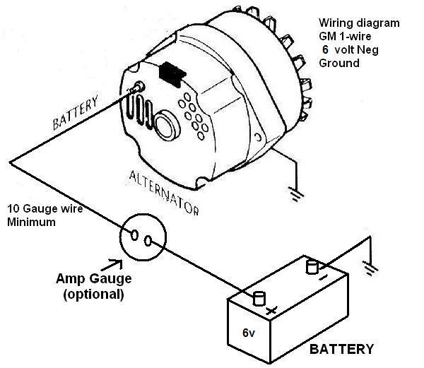
A Gm One Wire Alternator Wiring Diagram is a simplified electrical schematic depicting the connections between a single-wire alternator (used in General Motors vehicles) and its associated components. For instance, a diagram might illustrate the wiring between the alternator, battery, ignition switch, and voltage regulator. These schematics provide a clear visual guide for troubleshooting electrical issues, ensuring correct component installation and operation.
Gm One Wire Alternator Wiring Diagrams are crucial for efficient vehicle maintenance, helping mechanics and DIY enthusiasts diagnose and repair electrical problems accurately. Their simplicity and ease of interpretation enable quick and precise troubleshooting, saving time and reducing the risk of further electrical damage. The advent of single-wire alternators in the late 1960s revolutionized automotive electrical systems, simplifying wiring and improving alternator performance.
This article delves deeper into the Gm One Wire Alternator Wiring Diagram, exploring its components, troubleshooting techniques, and the evolution of alternator technology. By understanding these concepts, readers gain valuable knowledge for maintaining and repairing their vehicles’ electrical systems.
Understanding the essential aspects of Gm One Wire Alternator Wiring Diagrams is paramount for effective troubleshooting and maintenance. These aspects encompass various facets, each playing a crucial role in the proper functioning of the electrical system.
- Components
- Wiring
- Troubleshooting
- Installation
- Maintenance
- History
- Benefits
- Limitations
Delving into these aspects reveals their interconnectedness and significance. For instance, understanding the components involved in a Gm One Wire Alternator Wiring Diagram is essential for proper troubleshooting. Similarly, knowledge of the wiring scheme enables accurate installation and maintenance. Moreover, exploring the history of these diagrams provides insights into their evolution and the technological advancements that have shaped them. By examining both the individual aspects and their interrelationships, a comprehensive understanding of Gm One Wire Alternator Wiring Diagrams is achieved.
Components
Components form the backbone of Gm One Wire Alternator Wiring Diagrams, playing a significant role in the proper functioning of the electrical system. These components include various parts that work in conjunction to generate, regulate, and distribute electrical power throughout the vehicle.
-
Alternator
The alternator is the heart of the charging system, converting mechanical energy into electrical energy to recharge the battery and power electrical components.
-
Battery
The battery stores electrical energy, providing a reserve of power when the engine is not running and supplementing the alternator during high electrical demand.
-
Voltage Regulator
The voltage regulator monitors the electrical system voltage and adjusts the alternator’s output accordingly, preventing overcharging or undercharging.
-
Wiring
The wiring connects the alternator, battery, voltage regulator, and other electrical components, forming a complete circuit for the flow of electrical current.
Understanding the components of Gm One Wire Alternator Wiring Diagrams is crucial for effective troubleshooting, maintenance, and installation. By identifying and comprehending the role of each component, mechanics and enthusiasts can pinpoint issues, ensure proper operation, and make informed decisions regarding electrical system upgrades or repairs.
Wiring
Wiring serves as the backbone of Gm One Wire Alternator Wiring Diagrams, establishing the electrical connections between various components to ensure proper functioning of the charging system. Without accurate and reliable wiring, the alternator cannot effectively generate and distribute electrical power, leading to a range of electrical issues. The intricate network of wires forms a critical component of the diagram, allowing for the flow of electrical current and data.
Real-life examples of wiring within Gm One Wire Alternator Wiring Diagrams include the heavy-gauge wire connecting the alternator to the battery, which carries the high current generated by the alternator to recharge the battery. Another example is the thin wire connecting the voltage regulator to the alternator, which transmits control signals to regulate the alternator’s output voltage. These wires must be of appropriate gauge and quality to handle the electrical load and ensure efficient operation.
Understanding the wiring aspect of Gm One Wire Alternator Wiring Diagrams has practical significance for troubleshooting electrical problems, performing maintenance, and installing new components. By tracing the wires and identifying connections, mechanics and enthusiasts can pinpoint faulty components, diagnose issues, and make informed decisions regarding repairs or upgrades. Additionally, a thorough understanding of wiring enables proper installation of alternators, voltage regulators, and other electrical components, ensuring optimal performance and longevity.
Troubleshooting
“Troubleshooting” and “Gm One Wire Alternator Wiring Diagram” are inextricably linked, forming a critical partnership in the diagnosis and repair of automotive electrical systems. The wiring diagram provides a detailed roadmap of the alternator’s electrical connections, enabling technicians to trace circuits, identify faulty components, and pinpoint the root cause of electrical issues.
Understanding the wiring diagram is a prerequisite for effective troubleshooting. Without a clear understanding of the intended electrical pathways, it becomes challenging to identify deviations or disruptions that lead to system malfunctions. By referring to the diagram, technicians can systematically eliminate potential causes and zero in on the specific component or connection responsible for the problem.
Real-life examples of troubleshooting using Gm One Wire Alternator Wiring Diagrams abound. A common issue is the failure of the alternator to charge the battery, indicated by a “low battery” warning light on the dashboard. By consulting the wiring diagram, a technician can trace the charging circuit from the alternator to the battery, checking for loose connections, damaged wires, or faulty components along the way.
The practical applications of this understanding extend to various aspects of automotive electrical maintenance and repair. For instance, when installing a new alternator, the wiring diagram ensures proper connections and prevents incorrect wiring, which can lead to electrical damage or system failure. Similarly, when diagnosing electrical problems, the diagram serves as a valuable reference, guiding technicians through the troubleshooting process and facilitating accurate repairs.
Installation
Installation, a crucial aspect of Gm One Wire Alternator Wiring Diagrams, involves the physical integration of the alternator and its associated components into a vehicle’s electrical system. Understanding the intricacies of installation is essential to ensure proper functioning, avoid electrical hazards, and achieve optimal performance of the charging system.
-
Component Selection
Selecting compatible components is vital. Choosing the correct alternator, voltage regulator, and wiring harness ensures seamless integration and optimal performance.
-
Wiring Connections
Proper wiring connections are paramount. Following the wiring diagram meticulously ensures accurate connections, preventing short circuits and ensuring efficient power distribution.
-
Mounting Considerations
Securely mounting the alternator and its components prevents vibrations and ensures proper belt alignment, crucial for reliable charging.
-
Testing and Verification
After installation, thorough testing is essential to verify proper functionality. This includes checking for proper charging voltage, absence of parasitic drain, and correct operation of the voltage regulator.
Installation of Gm One Wire Alternator Wiring Diagrams requires precision and attention to detail. Following the recommended procedures, using high-quality components, and performing thorough testing ensures a reliable and optimally functioning electrical system. Proper installation not only guarantees the alternator’s performance but also contributes to the overall longevity and efficiency of the vehicle’s electrical components.
Maintenance
Maintenance is a critical aspect of Gm One Wire Alternator Wiring Diagrams, ensuring the reliable operation, extended lifespan, and optimal performance of the electrical system. Regular maintenance practices aim to diagnose potential issues early on, prevent premature failures, and maintain the system’s efficiency.
-
Component Inspection
Regularly inspecting the alternator, voltage regulator, wiring, and connections for signs of wear, corrosion, or damage helps identify potential issues before they escalate. -
Voltage and Current Testing
Using a multimeter to test the alternator’s output voltage, battery voltage, and system current ensures that the charging system is functioning within specified parameters. -
Belt Tension Adjustment
Proper belt tension is crucial for efficient alternator operation. Inspecting and adjusting the belt tension as per manufacturer recommendations prevents slippage and premature wear. -
Connector Cleaning
Cleaning the electrical connectors, terminals, and grounding points removes corrosion and ensures good electrical contact, minimizing resistance and potential voltage drops.
By adhering to recommended maintenance practices, mechanics and vehicle owners can proactively address potential issues, extend the lifespan of the alternator and its components, and ensure a reliable and efficiently functioning charging system. Neglecting maintenance can lead to costly repairs, electrical failures, and reduced vehicle performance.
History
The “History” of “Gm One Wire Alternator Wiring Diagram” is an integral aspect, shedding light on the evolution of alternator technology, design principles, and their real-world applications. By examining the historical context, we gain a deeper understanding of the diagram’s significance and its impact on the automotive industry.
-
Early Alternators
The origins of alternator technology can be traced back to the late 19th century, with early alternators employing complex wiring systems to regulate voltage and current output.
-
Delcotron Introduction
In the 1960s, General Motors introduced the Delcotron, a simplified alternator design featuring a single-wire output, revolutionizing alternator technology and reducing wiring complexity.
-
Standardization and Adoption
The Gm One Wire Alternator Wiring Diagram emerged as the industry standard, widely adopted by automotive manufacturers due to its simplicity, reliability, and cost-effectiveness.
-
Modern Advancements
While the basic principles remain unchanged, modern Gm One Wire Alternator Wiring Diagrams have evolved to incorporate advancements in voltage regulation, efficiency, and diagnostic capabilities.
Understanding the history of Gm One Wire Alternator Wiring Diagrams provides valuable insights into the technological journey of alternator systems, highlighting the continuous pursuit of efficiency, reliability, and simplified design. These diagrams have played a crucial role in the development of modern automotive electrical systems, ensuring reliable power generation and distribution in vehicles worldwide.
Benefits
The “Gm One Wire Alternator Wiring Diagram” offers numerous benefits that have revolutionized the automotive industry and enhanced the performance, reliability, and maintenance of electrical systems. Its simplified design and ease of use have made it a preferred choice for both professional mechanics and DIY enthusiasts alike.
One of the primary benefits of the Gm One Wire Alternator Wiring Diagram is its simplified wiring scheme, reducing the complexity and potential for errors during installation and maintenance. The single-wire design eliminates the need for intricate wiring configurations, making it easier to troubleshoot and repair electrical issues. This user-friendly design is particularly advantageous in tight engine compartments where space is limited.
The reliability of the Gm One Wire Alternator Wiring Diagram is another key benefit. The simplified wiring reduces the likelihood of loose connections, shorts, or other electrical faults that can plague more complex wiring systems. This enhanced reliability ensures consistent power generation and distribution, minimizing the risk of electrical failures or disruptions.
In practical applications, the benefits of the Gm One Wire Alternator Wiring Diagram translate into reduced maintenance costs and increased vehicle uptime. Simplified wiring allows for easier and faster troubleshooting, enabling mechanics to quickly identify and resolve electrical issues. The reduced complexity also makes it easier for vehicle owners to perform basic maintenance tasks, such as replacing the alternator or battery.
Limitations
While the Gm One Wire Alternator Wiring Diagram offers numerous benefits, it is not without certain limitations. Understanding these limitations is crucial for effectively utilizing and troubleshooting alternator systems.
-
Output Current
One limitation is the potential for limited output current compared to more complex alternator wiring systems. The single-wire design may restrict the alternator’s ability to deliver high currents at low engine speeds, which can impact the performance of power-hungry accessories.
-
Voltage Regulation
Another limitation is the potential for less precise voltage regulation compared to multi-wire alternator systems. The simplified wiring scheme may result in slight fluctuations in output voltage, especially under varying electrical loads.
-
Diagnostic Challenges
Troubleshooting electrical issues can be more challenging with a Gm One Wire Alternator Wiring Diagram. The simplified wiring reduces the number of diagnostic points, making it harder to pinpoint the exact source of a problem.
-
Compatibility
Gm One Wire Alternator Wiring Diagrams are not universally compatible with all vehicles. Some vehicle models may require modifications to the wiring harness or the installation of additional components to ensure proper functionality.
Despite these limitations, Gm One Wire Alternator Wiring Diagrams remain a popular choice for their simplicity, reliability, and ease of use. By carefully considering the limitations and matching the alternator system to the specific electrical demands of the vehicle, mechanics and enthusiasts can effectively harness the benefits of this wiring scheme.


![[DIAGRAM] Wiring Diagram For 1 Wire Gm Alternator](https://i0.wp.com/capestarter.com/ESW/Files/2wire12volt.jpg?w=665&ssl=1)


Related Posts


