Wiring a 5 Pin Rocker Switch: A 5-pin rocker switch requires specialized wiring, typically involving three terminals: power in, power out, and ground. The switch is responsible for completing or interrupting the electrical circuit between the input and output terminals when its lever is actuated.
In practical applications, a 5-pin rocker switch can be used for various purposes, such as controlling the on/off status of household appliances, illuminating light fixtures, or selecting different modes in electronic devices. Its versatility and ease of use make it a prevalent choice for electrical projects.
Historical Context: Rocker switches gained prominence in the early 20th century, replacing knife switches due to their enhanced safety and convenience. Their compact size and ability to handle higher currents contributed to their widespread adoption in various industries.
This article will delve into the intricacies of wiring a 5-pin rocker switch, exploring the specific connections, safety considerations, and practical applications that showcase its functionality.
Wiring a 5-pin rocker switch involves understanding and addressing various essential aspects that contribute to its successful installation and operation. These aspects encompass the switch’s electrical characteristics, physical attributes, safety considerations, and application-specific requirements.
- Electrical Compatibility: Ensuring the switch’s voltage and current ratings align with the circuit requirements.
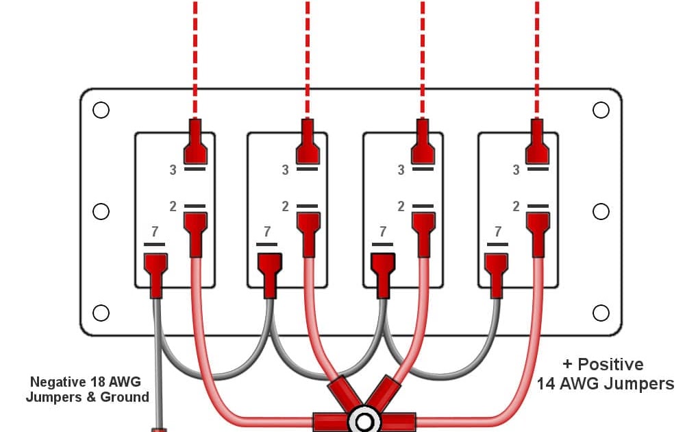
- Terminal Identification: Distinguishing between the power-in, power-out, and ground terminals for proper wiring.
- Wiring Materials: Selecting appropriate wire gauge and insulation type for safe and efficient current flow.
- Connection Methods: Understanding techniques such as soldering, crimping, and screw terminals for secure connections.
- Switch Orientation: Determining the correct switch orientation to match the desired circuit configuration.
- Panel Mounting: Selecting the appropriate mounting hardware and techniques for secure switch installation.
- Safety Precautions: Adhering to electrical safety guidelines, including proper insulation and avoiding live wire handling.
- Circuit Protection: Incorporating fuses or circuit breakers to safeguard the circuit and switch from overcurrent conditions.
- Troubleshooting Techniques: Identifying potential issues and implementing troubleshooting steps to resolve switch malfunctions.
- Specific Application Considerations: Tailoring the wiring approach to suit specific applications, such as appliance control, lighting systems, or industrial machinery.
These aspects are interconnected and crucial for ensuring the proper functionality and longevity of the 5-pin rocker switch. Understanding and considering each aspect during the wiring process contributes to a safe, efficient, and reliable electrical installation.
Electrical Compatibility
Electrical compatibility refers to matching the voltage and current ratings of a switch with the electrical circuit it will be controlling. This aspect is crucial for the safe and efficient operation of both the switch and the circuit.
When wiring a 5-pin rocker switch, it is essential to ensure that the switch’s voltage and current ratings are compatible with the circuit requirements. If the switch is rated for a lower voltage or current than the circuit, it may overheat, fail prematurely, or even pose a fire hazard. Conversely, if the switch is rated for a higher voltage or current than the circuit, it may not function properly or may damage other components in the circuit.
For example, consider a 5-pin rocker switch rated for 125 volts and 10 amperes. This switch would be suitable for use in a circuit with a voltage of 125 volts and a current of 10 amperes or less. However, if the switch were used in a circuit with a voltage of 240 volts, it could overheat and fail, potentially causing damage to the circuit or even a fire.
Therefore, it is crucial to carefully consider the electrical compatibility of a 5-pin rocker switch before wiring it into a circuit. By ensuring that the switch’s voltage and current ratings align with the circuit requirements, you can help ensure the safe and reliable operation of your electrical system.
Terminal Identification
Terminal identification is a critical aspect of wiring a 5-pin rocker switch, as it ensures proper connection and functionality of the switch. The power-in terminal receives the incoming power from the source, the power-out terminal provides the outgoing power to the load, and the ground terminal provides a path for any stray electrical current to flow safely to the ground. Misidentifying or incorrectly connecting these terminals can lead to malfunctions, damage to the switch or connected devices, or even electrical hazards.
For example, if the power-in and power-out terminals are reversed, the switch will not function correctly, and the load will not receive power. If the ground terminal is not properly connected, the switch may become energized and pose a shock hazard.
Therefore, it is crucial to correctly identify the terminals of a 5-pin rocker switch before wiring it. This can typically be done by referring to the manufacturer’s documentation or by using a multimeter to test the terminals for continuity. Once the terminals are identified, they should be connected using the appropriate gauge and type of wire and secure connections to ensure proper operation of the switch.
Wiring Materials
When wiring a 5-pin rocker switch, selecting the appropriate wire gauge and insulation type is crucial for ensuring the safe and efficient flow of electrical current. The wire gauge refers to the thickness of the wire, which determines its current-carrying capacity. Using a wire with too small of a gauge can lead to overheating and potential fire hazards, while using a wire with too large of a gauge can be wasteful and unnecessary.
The insulation type refers to the material that surrounds the wire and protects it from electrical shorts and other hazards. Different insulation types offer varying degrees of protection against moisture, heat, and chemicals, so choosing the right insulation type is essential for the specific application.
For example, in a high-temperature environment, a wire with heat-resistant insulation should be used to prevent the insulation from melting or degrading. In a wet environment, a wire with moisture-resistant insulation should be used to prevent electrical shorts.
By carefully selecting the appropriate wire gauge and insulation type, you can ensure that the 5-pin rocker switch operates safely and efficiently, providing reliable control of electrical circuits in a wide range of applications.
Additionally, using the correct wiring materials can also help to extend the lifespan of the switch and prevent costly repairs or replacements in the future.
Connection Methods
When wiring a 5-pin rocker switch, selecting the appropriate connection method is crucial for ensuring a secure and reliable electrical connection. Various techniques exist, each with its own advantages and applications. Understanding these connection methods is essential for ensuring the proper functioning and longevity of the switch.
- Soldering involves melting solder, a metal alloy, onto the wire and the terminal to create a permanent electrical connection. This method provides a strong and durable connection that is resistant to vibration and corrosion. However, it requires specialized equipment and skills to execute properly.
- Crimping utilizes a crimping tool to compress a metal sleeve or ferrule around the wire and the terminal. This method creates a secure mechanical connection that is less prone to failure due to vibration or movement. Crimping is a relatively simple technique that does not require specialized equipment, making it suitable for various applications.
- Screw terminals employ screws to clamp the wire between two metal plates. This method is simple and convenient, making it a popular choice for quick and easy connections. However, screw terminals may loosen over time due to vibration or thermal expansion, potentially compromising the connection.
- Push-in terminals feature spring-loaded connectors that allow wires to be inserted and released without the need for tools. This method is convenient and time-saving, but it may not provide the same level of secure connection as other methods, especially in high-vibration environments.
The choice of connection method for wiring a 5-pin rocker switch depends on factors such as the current carrying capacity, environmental conditions, and required level of reliability. By understanding the different connection methods and their respective advantages and limitations, you can select the most appropriate technique to ensure a secure and reliable electrical connection.
Switch Orientation
When wiring a 5-pin rocker switch, determining the correct switch orientation is crucial to ensure proper circuit operation and prevent malfunctions or safety hazards. The switch orientation refers to the physical alignment of the switch’s terminals with the circuit’s wiring. Misalignment can result in incorrect switching behavior, short circuits, or open circuits, compromising the functionality and safety of the electrical system.
For example, in a single-pole, double-throw (SPDT) rocker switch, the switch orientation determines which of the two output terminals is connected to the common terminal when the switch is actuated. If the switch orientation is incorrect, the circuit may not function as intended, potentially leading to unexpected behavior or even damage to connected components.
Therefore, understanding switch orientation and wiring the 5-pin rocker switch accordingly is essential for achieving reliable and safe circuit operation. It involves careful analysis of the circuit diagram, identification of the switch’s terminals, and proper alignment of the switch with the circuit’s wiring. By paying attention to switch orientation, you can ensure that the switch operates as intended, providing effective control and protection within the electrical system.
Panel Mounting
Panel mounting is an essential aspect of wiring a 5-pin rocker switch, ensuring the switch is securely fastened and remains stable during operation. Selecting the appropriate mounting hardware and techniques is crucial for maintaining the integrity of the electrical system and preventing potential hazards.
- Mounting Bracket: A mounting bracket provides a stable base for the rocker switch, preventing it from moving or becoming loose. It is typically made of metal or plastic and is designed to fit the specific dimensions of the switch.
- Mounting Screws: Mounting screws are used to secure the switch to the mounting bracket or directly to the panel. They should be of the correct size and type to ensure a firm hold without damaging the switch or panel.
- Gaskets or Seals: Gaskets or seals are used to create a watertight or dust-proof seal around the switch, preventing the ingress of moisture or contaminants that could compromise its functionality.
- Anti-Vibration Measures: In applications where vibration is a concern, additional measures such as rubber grommets or vibration dampeners can be employed to minimize the effects of vibration on the switch and its connections.
Proper panel mounting of a 5-pin rocker switch ensures reliable operation, prevents accidental dislodgement, and enhances the overall safety and aesthetics of the electrical installation. By carefully selecting the appropriate mounting hardware and techniques, you can ensure the switch remains securely in place and functions as intended over its lifespan.
Safety Precautions
When wiring a 5-pin rocker switch, adhering to strict safety precautions is paramount to prevent electrical hazards, ensure the longevity of the switch, and protect against potential accidents. These precautions encompass a range of critical aspects, including proper insulation and avoiding live wire handling, which warrant careful attention and understanding.
- Proper Insulation: Electrical insulation serves as a protective barrier around wires and components, preventing current leakage and short circuits. When wiring a 5-pin rocker switch, it is essential to ensure that all wires are properly insulated and that no bare conductors are exposed. This prevents accidental contact with live wires, reduces the risk of electrical shocks, and enhances the overall safety of the installation.
- Avoiding Live Wire Handling: Live wires carry electrical current and pose a significant hazard if handled improperly. When working with a 5-pin rocker switch, it is crucial to identify and avoid live wires. This involves utilizing proper testing equipment, such as a multimeter, to distinguish between live and neutral wires and taking necessary precautions to prevent accidental contact. Handling live wires without adequate protection can lead to electrical shocks, burns, or even electrocution.
- Grounding: Grounding provides a safe path for electrical current to flow in the event of a fault or short circuit. When wiring a 5-pin rocker switch, it is essential to ensure that the switch is properly grounded. This involves connecting the switch’s ground terminal to an appropriate grounding point, such as a metal electrical box or a dedicated grounding wire. Proper grounding helps protect against electrical shocks and prevents damage to the switch and connected equipment.
- Circuit Protection: Circuit protection devices, such as fuses or circuit breakers, are vital components in safeguarding electrical circuits from overcurrent conditions. When wiring a 5-pin rocker switch, it is essential to incorporate appropriate circuit protection devices into the circuit. These devices monitor the current flow and automatically interrupt the circuit in the event of an overload or short circuit, preventing damage to the switch, wiring, and connected components.
By adhering to these safety precautions, electricians and DIY enthusiasts can ensure the safe and reliable operation of 5-pin rocker switches. Proper insulation, avoidance of live wire handling, proper grounding, and incorporation of circuit protection measures collectively contribute to a safe and code-compliant electrical installation.
Circuit Protection
Within the realm of “Wiring 5 Pin Rocker Switch”, circuit protection stands as a crucial aspect, employing fuses or circuit breakers as safeguards against overcurrent conditions that could jeopardize both the circuit and the switch. Overcurrent conditions arise when the electrical current flowing through a circuit surpasses its safe operating limits, potentially leading to overheating, damage to components, and even electrical fires.
- Fuse Protection: Fuses are sacrificial devices designed to interrupt the circuit when the current exceeds a predetermined threshold. They contain a thin wire or strip that melts and breaks the circuit, preventing further current flow and protecting downstream components. Fuses are commonly employed in residential and commercial electrical systems due to their simplicity and cost-effectiveness.
- Circuit Breaker Protection: Circuit breakers are reusable protective devices that automatically trip and open the circuit when an overcurrent condition is detected. They consist of a bimetallic strip that bends and trips a switch when heated by excessive current, interrupting the circuit. Circuit breakers offer the advantage of being resettable, allowing for restoration of power without the need to replace a fuse.
- Current Rating and Selection: The appropriate selection of fuses or circuit breakers is critical for effective circuit protection. The current rating of these devices must be carefully matched to the maximum current that the circuit is expected to carry under normal operating conditions. Overrating the protective device could compromise its ability to respond to overcurrent conditions, while underrating could result in nuisance tripping.
- Placement and Accessibility: Fuses and circuit breakers should be strategically placed within the electrical system to provide protection for the switch and other circuit components. They should be readily accessible for inspection, testing, and replacement when necessary. Proper labeling and documentation are also essential for ease of identification and maintenance.
By incorporating appropriate circuit protection measures when wiring a 5-pin rocker switch, electrical systems can be safeguarded against overcurrent conditions, minimizing the risk of damage, electrical fires, and ensuring reliable operation of the switch and connected components.
Troubleshooting Techniques
Within the comprehensive topic of “Wiring 5 Pin Rocker Switch,” understanding troubleshooting techniques holds paramount importance for ensuring reliable operation and resolving switch malfunctions. Troubleshooting involves identifying potential issues and implementing systematic steps to diagnose and rectify problems, minimizing downtime and maintaining optimal switch performance.
- Identifying Loose Connections: Loose connections in the wiring or terminals can disrupt current flow and cause intermittent switch operation. Troubleshooting involves physically inspecting connections, ensuring they are tight and secure, and addressing any loose wires or terminals.
- Testing Switch Continuity: Using a multimeter, continuity testing can verify whether current flows through the switch’s contacts. An open circuit indicates a faulty switch that needs replacement, while a closed circuit confirms switch integrity.
- Inspecting Power Source: Intermittent or lack of power can lead to switch malfunction. Troubleshooting includes checking the power source, including batteries or electrical outlets, and verifying voltage levels to ensure they meet the switch’s specifications.
- Analyzing Circuit Diagram: Referring to the circuit diagram can provide insights into the switch’s connections and functionality. Troubleshooting involves tracing the circuit, identifying potential areas, and ensuring proper wiring and component placement.
Effective troubleshooting techniques empower individuals to diagnose and resolve switch malfunctions, ensuring the smooth operation of electrical systems. By systematically identifying potential issues and implementing appropriate corrective actions, troubleshooting contributes to the reliability, efficiency, and longevity of “Wiring 5 Pin Rocker Switch” applications.
Specific Application Considerations
When wiring a 5-pin rocker switch, specific application considerations play a critical role in tailoring the wiring approach to suit the unique requirements of different applications. These considerations encompass a wide range of factors that influence the switch’s functionality, safety, and overall performance.
For instance, in appliance control applications, the switch’s wiring must accommodate the specific electrical characteristics of the appliance, such as its voltage, current draw, and power consumption. Proper wire gauge selection and appropriate connection techniques are crucial to ensure safe and efficient operation of the appliance.
In lighting systems, the wiring approach for a 5-pin rocker switch must take into account the type of lighting load being controlled, whether it’s incandescent, fluorescent, or LED. Different lighting loads have varying power requirements and dimming capabilities, necessitating specific wiring configurations and switch compatibility.
Industrial machinery applications often demand robust and reliable wiring practices for 5-pin rocker switches. These switches are commonly used to control high-power motors, actuators, and other industrial equipment. The wiring approach must consider factors such as high currents, inductive loads, and potential electromagnetic interference to ensure safe and reliable operation in demanding industrial environments.
Understanding and addressing specific application considerations is essential for successful wiring of 5-pin rocker switches. By tailoring the wiring approach to the unique requirements of each application, electrical professionals can ensure optimal switch performance, enhance safety, and maximize the longevity of the electrical system.


Related Posts


