A wiring diagram of a backup camera provides a clear layout of the electrical connections necessary for the installation and proper functioning of a backup camera system in a motor vehicle. A typical wiring diagram includes detailed instructions on how to connect the camera to the vehicle’s power source, display screen, and any additional components, such as sensors or transmitters.
Understanding the wiring diagram is crucial for ensuring the backup camera operates reliably. It helps eliminate guesswork and reduces the risk of incorrect connections, which could lead to malfunctions, safety hazards, or damage to the system. Familiarity with the wiring diagram also empowers individuals to troubleshoot issues and make informed decisions about modifications or upgrades to the backup camera setup.
Historically, the development of wireless backup cameras in the late 2000s marked a significant advancement in vehicle safety technology. These cameras eliminate the need for complex wiring, making them easier to install and reducing the likelihood of interference or signal loss. Wireless backup cameras have become increasingly common in recent years and are now a popular choice for drivers who prioritize convenience and affordability.
Wiring a backup camera diagram is a crucial aspect of installing and maintaining a functional backup camera system. It provides a comprehensive overview of the electrical connections necessary for the camera to operate effectively.
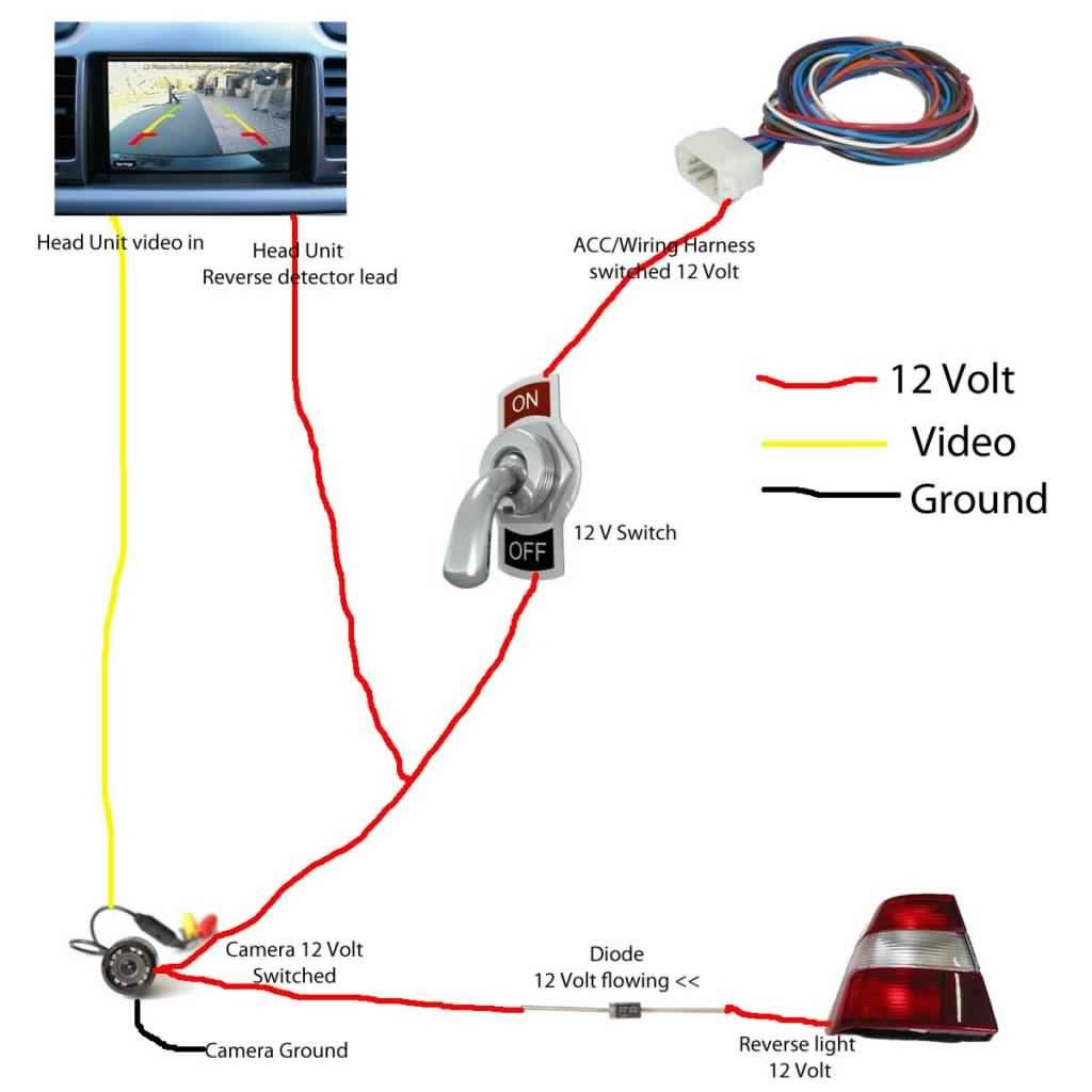
- Power Source: Defines the connection to the vehicle’s electrical system.
- Camera Input: Specifies the connection between the camera and the display screen.
- Display Output: Outlines the connection between the display screen and the vehicle’s dashboard.
- Ground Connection: Establishes a proper grounding point for the system.
- Trigger Wire: Indicates the connection to activate the camera when the vehicle is in reverse.
- Extension Wires: Details the use of additional wires to extend the reach of the camera.
- Fuses: Identifies the location and purpose of fuses to protect the system from electrical overloads.
- Labels and Color Codes: Explains the standardized labels and color codes used in wiring diagrams for easy identification.
Understanding these key aspects is essential to ensure a safe and reliable backup camera installation. By following the wiring diagram accurately, individuals can minimize the risk of electrical hazards, ensure optimal camera performance, and maximize the safety benefits of having a functional backup camera system.
Power Source
Establishing a reliable power source is the cornerstone of any functional backup camera installation. It ensures that the camera receives the necessary voltage to operate optimally and produce clear images. Within the context of “Wiring A Backup Camera Diagram,” the “Power Source” aspect plays a vital role in defining the electrical connection between the camera and the vehicle’s electrical system, allowing the camera to draw power for its operation.
- Battery Connection: The backup camera can be directly connected to the vehicle’s battery, providing a constant power supply. However, this method requires careful wiring and fuse protection to prevent overloads or short circuits.
- Reverse Light Connection: Alternatively, the camera can be connected to the vehicle’s reverse lights. This method ensures that the camera only operates when the vehicle is in reverse gear, eliminating the need for manual activation.
- Accessory Fuse Panel: Many vehicles have an accessory fuse panel that provides switched power, which is only active when the ignition is turned on. Connecting the backup camera to the switched power source ensures that the camera is not draining the battery when the vehicle is parked.
- Voltage Regulator: In some cases, the vehicle’s electrical system may not provide a stable voltage supply. A voltage regulator can be used to ensure that the backup camera receives a consistent voltage, preventing damage to the camera’s circuitry.
Understanding the various power source options and their implications is crucial for a successful backup camera installation. By carefully considering the power requirements of the camera and the electrical characteristics of the vehicle, installers can select the most appropriate power source and ensure reliable operation of the backup camera system.
Camera Input
Within the context of “Wiring A Backup Camera Diagram,” the “Camera Input” aspect plays a critical role in establishing the physical connection between the backup camera and the display screen. Understanding the various types of camera inputs and their implications is essential for ensuring a successful installation and optimal image quality.
- RCA Connector: A commonly used analog video connection, RCA connectors transmit video signals from the camera to the display screen. They are typically color-coded yellow for video and red and white for audio.
- Composite Video: Composite video is an analog video signal that combines the color and brightness information into a single channel. It is commonly used in older backup camera systems and requires a composite video input on the display screen.
- Component Video: Component video is an analog video signal that separates the color and brightness information into three separate channels. It provides better image quality than composite video and requires three separate video inputs on the display screen.
- Digital Video: Digital video signals transmit uncompressed or compressed video data from the camera to the display screen. They provide the highest image quality and are becoming increasingly common in modern backup camera systems.
Understanding the different types of camera inputs and their compatibility with both the backup camera and the display screen is crucial for a successful installation. By carefully selecting the appropriate camera input, installers can ensure that the backup camera system delivers clear and reliable images, enhancing the driver’s visibility and safety.
Display Output
Within the context of “Wiring A Backup Camera Diagram,” the “Display Output” aspect holds significant importance in establishing a seamless connection between the backup camera and the vehicle’s dashboard. The diagram provides detailed instructions on how to interface the display screen with the vehicle’s electrical system, ensuring that the camera’s video output is properly displayed on the screen.
The “Display Output” section of the wiring diagram typically includes:
- Power Connection: Defines how the display screen receives power from the vehicle’s electrical system.
- Video Input: Specifies the type of video input supported by the display screen, such as RCA, composite, component, or digital.
- Mounting Instructions: Provides guidance on how to physically mount the display screen on the vehicle’s dashboard.
Understanding the “Display Output” aspect is crucial for ensuring that the backup camera system functions effectively. By following the wiring diagram accurately, installers can avoid incorrect connections, electrical hazards, and poor image quality. A properly installed display screen provides the driver with a clear view of the rear surroundings, enhancing safety and convenience while reversing the vehicle.
Ground Connection
Within the context of “Wiring A Backup Camera Diagram,” the “Ground Connection” aspect plays a critical role in ensuring the proper functioning of the backup camera system. It establishes a reference point for electrical circuits, providing a path for current to flow and preventing electrical noise or malfunctions. Understanding the importance of “Ground Connection: Establishes a proper grounding point for the system” is essential for a reliable and safe backup camera installation.
- Electrical Circuit Completion: The ground connection completes the electrical circuit, allowing current to flow from the power source through the camera and display screen, back to the battery.
- Noise Reduction: A proper ground connection helps reduce electrical noise and interference in the video signal, resulting in a clearer and more stable image on the display screen.
- Safety: Grounding the backup camera system prevents stray electrical currents from flowing through the vehicle’s chassis, minimizing the risk of electrical shocks or damage to sensitive electronic components.
- Compliance: Meeting the grounding requirements specified in the “Wiring A Backup Camera Diagram” ensures compliance with industry standards and manufacturer specifications, enhancing the overall safety and reliability of the installation.
In summary, “Ground Connection: Establishes a proper grounding point for the system” is a fundamental aspect of “Wiring A Backup Camera Diagram.” It ensures the proper functioning of the backup camera system, reduces electrical noise, enhances safety, and adheres to industry standards. By understanding and implementing the grounding requirements outlined in the wiring diagram, installers can ensure a reliable and effective backup camera system.
Trigger Wire
Within the context of “Wiring A Backup Camera Diagram,” the “Trigger Wire” plays a crucial role in activating the backup camera only when the vehicle is in reverse gear. This ensures that the camera operates only when necessary, preserving battery power and enhancing the driver’s experience. Understanding the “Trigger Wire: Indicates the connection to activate the camera when the vehicle is in reverse” aspect is essential for a functional and efficient backup camera system.
- Reverse Light Connection: The trigger wire is typically connected to the vehicle’s reverse light circuit. When the vehicle is shifted into reverse gear, the reverse lights illuminate, providing power to the trigger wire, which in turn activates the backup camera.
- Dedicated Trigger Wire: In some cases, vehicles may have a dedicated trigger wire specifically designed for activating backup cameras. This dedicated wire provides a more stable and reliable connection, ensuring consistent camera operation when the vehicle is in reverse.
- Delay Module: Some trigger wires incorporate a delay module that keeps the backup camera active for a few seconds after the vehicle is shifted out of reverse gear. This delay allows the driver additional time to view the rear surroundings before the camera deactivates.
- Manual Activation: In certain situations, a manual switch or button can be connected to the trigger wire, giving the driver the option to activate the backup camera regardless of the vehicle’s gear position. This can be useful for troubleshooting or specific driving scenarios.
In summary, the “Trigger Wire: Indicates the connection to activate the camera when the vehicle is in reverse” aspect of “Wiring A Backup Camera Diagram” is essential for ensuring the proper functioning of the backup camera system. By understanding the various types of trigger wires and their implications, installers can configure the system to meet the specific requirements of the vehicle and the driver’s preferences, enhancing safety, convenience, and overall driving experience.
Extension Wires
In the context of “Wiring A Backup Camera Diagram,” understanding the “Extension Wires: Details the use of additional wires to extend the reach of the camera” aspect is crucial for ensuring a successful installation and optimal camera performance. Extension wires play a critical role in overcoming distance limitations and providing flexibility in camera placement, especially when the standard length of the camera’s wiring harness is insufficient to reach the desired mounting location.
The “Wiring A Backup Camera Diagram” typically includes detailed instructions on how to connect extension wires to the backup camera and the display screen. These instructions specify the type of extension wires required, their length, and the proper connection sequence. By following the diagram accurately, installers can avoid incorrect connections, which could lead to signal loss, image distortion, or damage to the camera or display screen.
Real-life examples of “Extension Wires: Details the use of additional wires to extend the reach of the camera” within “Wiring A Backup Camera Diagram” include:
- Extending the camera cable to reach a mounting location on the rear of a large vehicle, such as a truck or RV.
- Using extension wires to connect the camera to a display screen mounted on the dashboard, even when the camera is installed at the back of the vehicle.
- Adding extension wires to an existing backup camera system to accommodate the installation of an additional camera, such as a side-view camera.
Understanding the significance of “Extension Wires: Details the use of additional wires to extend the reach of the camera” empowers installers to design and implement backup camera systems that meet the specific requirements of different vehicles and installation scenarios. By carefully selecting and connecting extension wires, installers can ensure that the backup camera is positioned optimally for maximum visibility and safety, regardless of the distance between the camera and the display screen.
Fuses
In the context of “Wiring A Backup Camera Diagram,” understanding the “Fuses: Identifies the location and purpose of fuses to protect the system from electrical overloads” aspect is critical for ensuring the safe and reliable operation of the backup camera system. Fuses play a vital role in protecting the camera, display screen, and other components from damage caused by electrical overloads or short circuits.
Electrical overloads can occur due to various reasons, such as faulty wiring, incorrect connections, or excessive power draw. When an electrical overload occurs, the fuse acts as a sacrificial element, breaking the circuit and preventing the flow of excessive current. This prevents damage to the more expensive and sensitive components of the backup camera system.
The “Wiring A Backup Camera Diagram” typically includes detailed instructions on the location and purpose of fuses within the system. These instructions specify the type of fuses required, their amperage rating, and the location of the fuse box or panel. By following the diagram accurately, installers can ensure that the backup camera system is properly protected against electrical overloads.
A real-life example of “Fuses: Identifies the location and purpose of fuses to protect the system from electrical overloads” within “Wiring A Backup Camera Diagram” is the inclusion of an inline fuse on the power wire of the backup camera. This fuse protects the camera from damage in case of a short circuit or power surge.
Understanding the significance of “Fuses: Identifies the location and purpose of fuses to protect the system from electrical overloads” empowers installers to design and implement backup camera systems that meet safety standards and industry best practices. By incorporating fuses into the system, installers can prevent electrical hazards, protect valuable components, and ensure the longevity and reliability of the backup camera system.
Labels and Color Codes
In the context of “Wiring A Backup Camera Diagram,” the significance of “Labels and Color Codes: Explains the standardized labels and color codes used in wiring diagrams for easy identification” lies in its role as a critical component for ensuring a clear and accurate understanding of the wiring process. Standardized labels and color codes provide a universal language for electrical diagrams, enabling installers and technicians to quickly identify wires, terminals, and components, regardless of the complexity of the system.
The use of labels and color codes in “Wiring A Backup Camera Diagram” streamlines the installation process, reduces the risk of errors, and facilitates troubleshooting. By adhering to established labeling and color-coding conventions, manufacturers ensure that all components of the backup camera system can be easily identified and connected, minimizing the potential for incorrect wiring or misinterpretation.
Real-life examples of “Labels and Color Codes: Explains the standardized labels and color codes used in wiring diagrams for easy identification” within “Wiring A Backup Camera Diagram” include:
- Power wires are typically labeled with a “P” or colored red, indicating they carry positive voltage.
- Ground wires are often labeled with a “G” or colored black, representing the negative terminal or chassis ground.
- Signal wires, which transmit video or other data, are usually labeled with specific colors or alphanumeric codes to differentiate them from power and ground wires.
Understanding the practical applications of “Labels and Color Codes: Explains the standardized labels and color codes used in wiring diagrams for easy identification” empowers individuals to confidently install and maintain backup camera systems. By recognizing and interpreting the labels and color codes, installers can efficiently trace wires, identify faulty connections, and troubleshoot issues, ensuring the reliable operation of the backup camera system.


Related Posts


