An Audi A4 Stereo Wiring Diagram provides a comprehensive layout of electrical connections and components within the vehicle’s audio system. It guides technicians and enthusiasts alike in troubleshooting, installing, and modifying car stereos by visually representing the flow of electrical signals.
The diagram is particularly relevant for vehicles where the factory-installed stereo has been replaced or upgraded, ensuring proper functionality and preventing electrical issues. Additionally, it helps identify and locate specific wires, connectors, and components, facilitating repairs and customizations.
A key historical development in automotive electronics was the advent of standardized wiring colors and protocols, making it easier for technicians to interpret diagrams across different vehicle models and brands. This consistency has greatly enhanced the usefulness and accessibility of stereo wiring diagrams.
Understanding the essential aspects of an Audi A4 Stereo Wiring Diagram is crucial for anyone looking to troubleshoot, install, or modify their vehicle’s audio system. These aspects provide a comprehensive overview of the electrical connections and components involved, ensuring a successful and safe installation.
- Accuracy: The diagram should accurately reflect the electrical connections and components of the specific Audi A4 model.
- Comprehensiveness: It should include all relevant electrical connections, including power, ground, speakers, and any additional components such as amplifiers or subwoofers.
- Clarity: The diagram should be easy to understand and interpret, using clear symbols and labels.
- Color-coding: Standard color-coding should be used for wires to simplify identification and tracing.
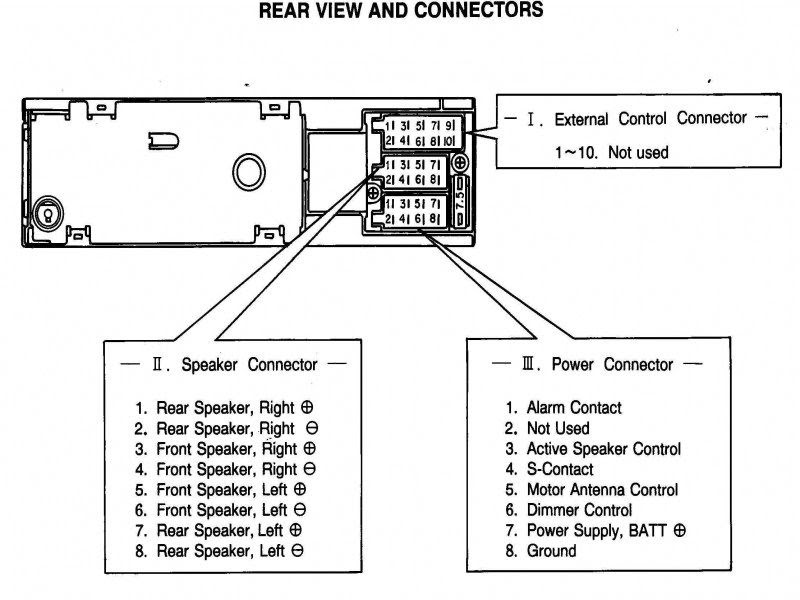
- Connector identification: The diagram should clearly identify all connectors and their pinouts.
- Component labeling: All components, such as speakers, amplifiers, and head units, should be clearly labeled.
- Grounding points: The diagram should indicate all grounding points for the audio system.
- Wire gauges: The wire gauges used for different connections should be specified.
- Fuse ratings: The fuse ratings for the audio system components should be included.
- Integration with other systems: The diagram should show how the audio system integrates with other vehicle systems, such as the navigation or climate control.
These aspects combine to provide a valuable resource for anyone working on the audio system of an Audi A4. By understanding and following the diagram accurately, it is possible to ensure a properly functioning and safe audio system installation.
Accuracy
Accuracy is a critical component of an Audi A4 Stereo Wiring Diagram because it ensures that the diagram accurately represents the electrical connections and components of the specific Audi A4 model. This is important because it allows technicians and enthusiasts to correctly identify and connect wires, connectors, and components, ensuring proper functionality and preventing electrical issues.
For example, if the diagram is inaccurate, it could lead to incorrect connections being made, which could damage the audio system or even cause electrical fires. Additionally, an inaccurate diagram could make it difficult to troubleshoot problems with the audio system, as it would not provide an accurate representation of the actual electrical connections.
Therefore, it is essential that an Audi A4 Stereo Wiring Diagram be accurate in order to ensure the proper installation, maintenance, and repair of the vehicle’s audio system. By understanding the importance of accuracy in wiring diagrams, technicians and enthusiasts can ensure that their audio system installations are safe and reliable.
Comprehensiveness
Comprehensiveness is a critical component of an Audi A4 Stereo Wiring Diagram because it ensures that the diagram includes all relevant electrical connections, including power, ground, speakers, and any additional components such as amplifiers or subwoofers. This is important because it allows technicians and enthusiasts to correctly identify and connect all of the necessary wires, connectors, and components, ensuring proper functionality and preventing electrical issues.
For example, if the diagram is not comprehensive and does not include all of the necessary electrical connections, it could lead to incorrect connections being made, which could damage the audio system or even cause electrical fires. Additionally, an incomplete diagram could make it difficult to troubleshoot problems with the audio system, as it would not provide a complete representation of the actual electrical connections.
Therefore, it is essential that an Audi A4 Stereo Wiring Diagram be comprehensive in order to ensure the proper installation, maintenance, and repair of the vehicle’s audio system. By understanding the importance of comprehensiveness in wiring diagrams, technicians and enthusiasts can ensure that their audio system installations are safe and reliable.
Here are some real-life examples of how the comprehensiveness of an Audi A4 Stereo Wiring Diagram can be applied in practical situations:
- Troubleshooting: A comprehensive wiring diagram can help technicians quickly identify and troubleshoot problems with the audio system. For example, if the speakers are not working, the technician can use the diagram to trace the electrical connections from the head unit to the speakers, identifying any breaks or loose connections.
- Installation: A comprehensive wiring diagram can help enthusiasts install a new audio system in their Audi A4. The diagram will provide all of the necessary information on how to connect the new components, ensuring a proper and safe installation.
- Upgrading: A comprehensive wiring diagram can help enthusiasts upgrade their existing audio system. For example, if the enthusiast wants to add an amplifier or subwoofer, the diagram will provide the necessary information on how to connect the new components to the existing system.
By understanding the importance of comprehensiveness in Audi A4 Stereo Wiring Diagrams, technicians and enthusiasts can ensure that their audio system installations are safe, reliable, and meet their specific needs.
Clarity
Clarity is a critical component of an Audi A4 Stereo Wiring Diagram because it ensures that the diagram is easy to understand and interpret, using clear symbols and labels. This is important because it allows technicians and enthusiasts to quickly and accurately identify and connect wires, connectors, and components, ensuring proper functionality and preventing electrical issues.
For example, if the diagram is not clear and uses unclear symbols or labels, it could lead to incorrect connections being made, which could damage the audio system or even cause electrical fires. Additionally, an unclear diagram could make it difficult to troubleshoot problems with the audio system, as it would be difficult to identify the correct wires and connections.
Therefore, it is essential that an Audi A4 Stereo Wiring Diagram be clear and easy to understand in order to ensure the proper installation, maintenance, and repair of the vehicle’s audio system. By understanding the importance of clarity in wiring diagrams, technicians and enthusiasts can ensure that their audio system installations are safe and reliable.
Here are some real-life examples of how the clarity of an Audi A4 Stereo Wiring Diagram can be applied in practical situations:
- Troubleshooting: A clear wiring diagram can help technicians quickly identify and troubleshoot problems with the audio system. For example, if the speakers are not working, the technician can use the diagram to trace the electrical connections from the head unit to the speakers, quickly identifying any breaks or loose connections.
- Installation: A clear wiring diagram can help enthusiasts install a new audio system in their Audi A4. The diagram will provide clear and concise instructions on how to connect the new components, ensuring a proper and safe installation.
- Upgrading: A clear wiring diagram can help enthusiasts upgrade their existing audio system. For example, if the enthusiast wants to add an amplifier or subwoofer, the diagram will provide clear instructions on how to connect the new components to the existing system.
By understanding the importance of clarity in Audi A4 Stereo Wiring Diagrams, technicians and enthusiasts can ensure that their audio system installations are safe, reliable, and meet their specific needs.
Color-coding
In the context of an Audi A4 Stereo Wiring Diagram, color-coding plays a crucial role in simplifying the identification and tracing of wires, ensuring accurate and efficient installation and maintenance of the audio system. Standard color-coding practices assign specific colors to different types of wires, providing a universal language for electrical connections.
- Power Wires: Typically red or yellow, these wires carry electrical power from the battery to the audio system components.
- Ground Wires: Usually black or brown, these wires provide a return path for electrical current, completing the circuit.
- Speaker Wires: Color-coded in pairs (e.g., white/white with black stripe, gray/gray with black stripe), these wires connect the audio system to the speakers.
- Signal Wires: Often shielded and color-coded according to function (e.g., blue for antenna, green for left audio channel), these wires transmit audio signals between components.
By adhering to standard color-coding, Audi A4 Stereo Wiring Diagrams enable technicians and enthusiasts to quickly and accurately identify the purpose of each wire, reducing the risk of incorrect connections that could damage the system or cause electrical hazards. Additionally, color-coding facilitates troubleshooting, as wires can be easily traced and tested.
Connector identification
In the context of an Audi A4 Stereo Wiring Diagram, connector identification plays a vital role in ensuring accurate and efficient installation and maintenance of the audio system. Connectors provide the physical interface between different components, and their pinouts define the specific connections and signal flow. Clearly identifying these connectors and their pinouts is crucial for several reasons:
- Correct Connections: Proper identification of connectors and pinouts ensures that components are connected correctly, preventing damage to the system or electrical hazards.
- Simplified Troubleshooting: When troubleshooting issues, pinouts allow technicians to quickly identify the purpose of each connector and trace signal flow, simplifying the diagnostic process.
- Compatibility Verification: When upgrading or replacing components, connector identification helps verify compatibility and ensures that new components will connect seamlessly with the existing wiring harness.
- Customization and Expansion: For enthusiasts looking to customize or expand their audio system, understanding connector pinouts enables them to integrate additional components or accessories.
Overall, connector identification is a fundamental aspect of Audi A4 Stereo Wiring Diagrams, providing a clear and organized representation of the system’s electrical connections. By adhering to standard pinout conventions, diagrams empower technicians and enthusiasts alike to confidently navigate the complexities of automotive audio installations and modifications.
Component labeling
In the context of an Audi A4 Stereo Wiring Diagram, component labeling plays a crucial role in ensuring accurate and efficient installation, maintenance, and troubleshooting of the audio system. Clearly labeled components provide several key benefits:
- Simplified Identification: Clear labeling allows technicians and enthusiasts to quickly and easily identify specific components, reducing the risk of confusion or errors during installation.
- Accurate Connections: Proper labeling ensures that components are connected correctly, preventing damage to the system or electrical hazards.
- Enhanced Troubleshooting: When troubleshooting issues, labeled components enable technicians to quickly trace signal flow and identify potential problems.
- Customization and Expansion: For enthusiasts looking to customize or expand their audio system, labeled components facilitate the integration of additional components or accessories.
Overall, component labeling is an essential aspect of Audi A4 Stereo Wiring Diagrams, as it provides a clear and organized representation of the system’s electrical connections. By adhering to standard labeling conventions, diagrams empower technicians and enthusiasts alike to confidently navigate the complexities of automotive audio installations and modifications.
Grounding points
In the context of an Audi A4 Stereo Wiring Diagram, grounding points play a crucial role in ensuring proper functionality and safety of the audio system. Grounding points provide a reference point for electrical circuits, allowing current to flow properly and preventing electrical noise and interference. Accurately indicating all grounding points in the diagram is essential for several reasons:
- Electrical Safety: Proper grounding ensures that stray electrical currents are safely discharged, preventing damage to components and electrical hazards.
- Noise Reduction: Effective grounding minimizes electrical noise and interference, resulting in improved audio quality.
- Troubleshooting: Clearly labeled grounding points simplify troubleshooting by allowing technicians to quickly identify and address grounding issues.
- Compatibility: When upgrading or replacing audio system components, grounding point identification ensures compatibility and proper operation.
Overall, grounding points are a critical aspect of Audi A4 Stereo Wiring Diagrams, as they provide a clear and accurate representation of the system’s electrical connections and grounding scheme. By adhering to standard grounding conventions and practices, diagrams empower technicians and enthusiasts alike to confidently navigate the complexities of automotive audio installations and modifications, ensuring optimal performance and safety.
Wire gauges
In the context of “Audi A4 Stereo Wiring Diagram,” specifying wire gauges is crucial for ensuring proper system functionality, safety, and performance. Wire gauge refers to the thickness and current-carrying capacity of electrical wires, and it plays a significant role in various aspects of the audio system’s design and installation.
- Power Handling: Different components in the audio system, such as amplifiers and speakers, require varying amounts of electrical power. The wire gauge must be thick enough to handle the current draw of each component without overheating or causing voltage drop.
- Signal Quality: Thinner gauge wires can introduce resistance into the circuit, which can degrade audio signal quality. Using the appropriate wire gauge ensures minimal signal loss and maintains the integrity of the audio signal.
- Safety: Undersized wire gauges can overheat and pose a fire hazard. Specifying the correct wire gauge ensures that the wires can safely carry the electrical current without overheating.
- Installation Convenience: Thicker gauge wires are more difficult to bend and route, while thinner gauge wires may be more susceptible to damage. Specifying the appropriate wire gauge helps balance installation ease with system performance.
Overall, specifying wire gauges in “Audi A4 Stereo Wiring Diagram” provides a comprehensive and accurate representation of the electrical connections and ensures that the audio system operates safely, efficiently, and delivers optimal performance.
Fuse ratings
In the context of an Audi A4 Stereo Wiring Diagram, specifying fuse ratings is crucial for ensuring the safety and proper functionality of the audio system. Fuse ratings indicate the maximum amount of electrical current that a fuse can safely handle before it breaks the circuit, protecting components from damage in the event of an electrical fault.
Including fuse ratings in the wiring diagram serves several important purposes:
- Overcurrent Protection: Fuse ratings help determine the appropriate fuse size for each component, ensuring that the fuse will blow before the component is damaged by excessive current.
- Electrical Safety: Proper fuse selection prevents electrical fires and other hazards by interrupting the circuit when current exceeds safe levels.
- Troubleshooting: Fuse ratings assist in troubleshooting electrical issues by providing a reference for identifying blown fuses and diagnosing potential problems.
- Compliance: Meeting fuse rating specifications is essential for adhering to safety standards and regulations.
Real-life examples of fuse ratings in Audi A4 Stereo Wiring Diagrams include:
- The head unit may require a 5-amp fuse to protect its circuitry.
- An amplifier may require a 10-amp fuse to handle its higher power consumption.
- Individual speakers typically have lower fuse ratings, such as 1-amp or 2-amp fuses, to protect against damage from overcurrent.
Understanding the importance of fuse ratings in Audi A4 Stereo Wiring Diagrams allows technicians, installers, and enthusiasts to make informed decisions about fuse selection and replacement. By adhering to the specified fuse ratings, they can ensure the safe and reliable operation of the audio system, preventing potential damage to components and electrical hazards.
Integration with other systems
In the context of Audi A4 Stereo Wiring Diagrams, the integration of the audio system with other vehicle systems is a crucial aspect that enhances the overall functionality and user experience. By understanding this connection, technicians and enthusiasts can harness the full potential of their audio systems.
The integration of the audio system with other systems typically involves the exchange of signals and data over dedicated communication buses or interfaces. This allows for seamless control and interaction between different components, creating a more cohesive and user-friendly experience. For instance, the audio system may integrate with the navigation system to provide voice guidance or display track information on the navigation screen. Similarly, it may integrate with the climate control system to adjust audio settings based on the cabin temperature or fan speed.
Real-life examples of system integration in Audi A4 Stereo Wiring Diagrams include:
- Enabling steering wheel controls for volume adjustment, track skipping, and source selection.
- Displaying song information on the instrument cluster or head-up display.
- Automatically adjusting audio volume based on vehicle speed.
- Integrating with smartphone apps for remote control and music streaming.
Understanding the integration of the audio system with other vehicle systems empowers individuals to make informed decisions about system upgrades and modifications. By incorporating this knowledge into the design and installation process, they can achieve a more seamless and enjoyable audio experience while maintaining the integrity and functionality of the vehicle’s other systems.

![[DIAGRAM] 01 Audi A4 Radio Wiring Diagrams](https://i0.wp.com/ww2.justanswer.com/uploads/vwtech0405/2011-12-26_140438_5.gif?w=665&ssl=1)


![[DIAGRAM] 01 Audi A4 Radio Wiring Diagrams](https://i0.wp.com/pinoutguide.com/images/upload/pinout_1382505031_image.png?w=665&ssl=1)

Related Posts


