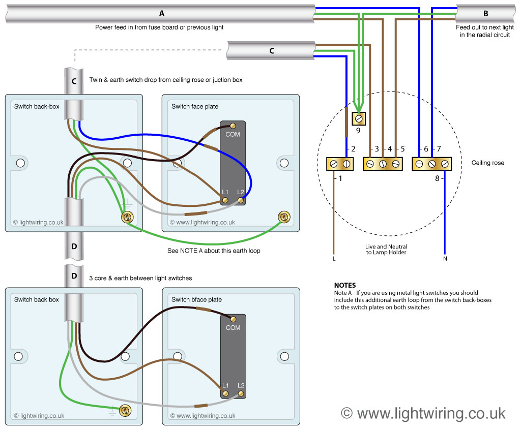
A wiring diagram for a 2-way light switch illustrates the electrical connections between two switches that control a single light fixture. For example, in a hallway with lights at both ends, a 2-way switch at each end allows you to turn the lights on or off from either location.
The use of 2-way light switches enhances convenience and safety in various settings, eliminating the need to walk back and forth to adjust lighting. Historically, the development of the tumbler switch in the early 20th century paved the way for the widespread adoption of 2-way switches.
In this article, we delve deeper into the components, wiring techniques, and practical applications of 2-way light switches, providing a comprehensive guide for electrical professionals and homeowners alike.
A wiring diagram for a 2-way light switch is an essential tool for understanding the electrical connections and functionality of this type of switch. It provides a visual representation of the components and their relationships, making it easier to troubleshoot and repair electrical issues.
- Components: Switch, wire, electrical box
- Wiring: Line, load, traveler
- Functionality: Controls a light fixture from two locations
- Circuit: Single-pole, double-throw
- Power: 120 volts AC
- Safety: Proper grounding and insulation
- Codes: National Electrical Code (NEC)
- Tools: Screwdriver, wire strippers
- Applications: Hallways, stairwells, large rooms
- Troubleshooting: Open circuits, loose connections
These key aspects provide a comprehensive overview of wiring diagrams for 2-way light switches. By understanding the components, wiring, functionality, and safety considerations involved, electricians and homeowners can ensure the proper installation and maintenance of these switches for convenient and safe lighting control.
Components
In a wiring diagram for a 2-way light switch, the switch, wire, and electrical box are indispensable components that work together to enable the control of a light fixture from two different locations. The switch is the user interface, allowing the user to turn the light on or off. The wire provides the electrical pathway for the current to flow from the power source to the light fixture. The electrical box houses and protects the switch and wire connections.
The relationship between these components is critical. Without the switch, the user would not be able to control the light. Without the wire, the electrical current could not reach the light fixture. Without the electrical box, the switch and wire connections would be exposed and vulnerable to damage or electrical shock.
Real-life examples of these components within a wiring diagram for a 2-way light switch can be found in homes, offices, and other buildings. In a hallway, for instance, a 2-way light switch allows you to turn the lights on at one end of the hallway and off at the other end. This is made possible by the switch, wire, and electrical box working together to complete the electrical circuit.
Understanding the connection between these components is essential for electricians and homeowners alike. By comprehending the role of each component and how they work together, it becomes easier to troubleshoot and repair electrical issues, ensuring the safe and efficient operation of 2-way light switches.
Wiring
Within the context of a wiring diagram for a 2-way light switch, the terms “line,” “load,” and “traveler” hold significant importance. These elements represent the electrical pathways and connections that enable the switch to control a light fixture from two separate locations.
-
Line
The line wire carries the electrical power from the source to the switch. It is typically black or red in color and is connected to the “line” terminal on the switch.
-
Load
The load wire carries the electrical power from the switch to the light fixture. It is typically white in color and is connected to the “load” terminal on the switch.
-
Traveler
The traveler wires are used to connect the two switches together. They are typically red or blue in color and are connected to the “traveler” terminals on the switches.
Understanding the roles and connections of the line, load, and traveler wires is essential for proper installation and troubleshooting of 2-way light switches. Improper wiring can lead to electrical hazards and malfunctioning of the switch. By adhering to the correct wiring diagram and ensuring secure connections, electricians and homeowners can ensure the safe and efficient operation of 2-way light switches in residential and commercial settings.
Functionality
Within the context of a wiring diagram for a 2-way light switch, the functionality of controlling a light fixture from two locations stands as a defining characteristic, conferring significant benefits and practical applications. This key aspect involves the use of two switches, strategically positioned in different areas, to provide independent control over a single light source.
- Individual Control: Each switch operates independently, allowing occupants to turn the lights on or off from either location without affecting the state of the other switch.
- Convenience and Accessibility: The ability to control a light from multiple points enhances convenience, especially in larger spaces or areas with multiple entrances, eliminating the need to walk back and forth to adjust lighting.
- Safety and Security: 2-way light switches offer greater control over lighting, which can be beneficial in situations where quick access to light is crucial, such as during emergencies or when entering a dimly lit area.
- Energy Efficiency: By enabling users to turn off lights from multiple locations, 2-way switches promote energy efficiency by reducing the likelihood of lights being left on unnecessarily.
The functionality of controlling a light fixture from two locations makes 2-way light switches indispensable in various residential, commercial, and industrial settings. Whether it’s a hallway, staircase, or large room, the ability to conveniently and efficiently control lighting from multiple points enhances both comfort and practicality.
Circuit
In the context of wiring diagrams for 2-way light switches, understanding the concept of a single-pole, double-throw (SPDT) circuit is paramount. An SPDT circuit forms the electrical foundation upon which 2-way light switches operate, allowing for the control of a single light fixture from two separate locations.
The SPDT circuit comprises a switch with three terminals: one common terminal and two traveler terminals. The common terminal is connected to the power source, while the traveler terminals are connected to the two different switch locations. When the switch is in one position, the common terminal is connected to one traveler terminal, completing the circuit and allowing current to flow to the light fixture. When the switch is moved to the other position, the common terminal is connected to the other traveler terminal, redirecting the current and turning off the light.
In a 2-way light switch wiring diagram, two SPDT circuits are employed, one for each switch. The traveler terminals of the two switches are connected together, forming a continuous pathway for the electrical current. This configuration enables the user to control the light from either switch location, as each switch effectively completes or breaks the circuit, turning the light on or off.
Comprehending the relationship between a single-pole, double-throw circuit and a wiring diagram for a 2-way light switch is essential for electricians and homeowners alike. This understanding empowers individuals to troubleshoot and repair electrical issues, ensuring the safe and efficient operation of 2-way light switches in various residential, commercial, and industrial settings.
Power
In the context of wiring diagrams for 2-way light switches, the voltage and type of electrical power play a crucial role in determining the design and functionality of the circuit. The vast majority of residential and commercial buildings in North America utilize a 120-volt alternating current (AC) electrical system. This means that the electrical power supplied to the light switch and fixture operates at a voltage of 120 volts and alternates its direction of flow periodically.
Within the wiring diagram for a 2-way light switch, the 120 volts AC power is supplied to the switch through the “line” terminal. From there, the power is routed through the switch contacts and out to the light fixture through the “load” terminal. When the switch is in the “on” position, the circuit is completed, allowing the 120 volts AC power to flow to the light fixture, illuminating it. When the switch is in the “off” position, the circuit is broken, and the power is prevented from reaching the light fixture, turning it off.
Understanding the relationship between the 120 volts AC power and the wiring diagram for a 2-way light switch is essential for several reasons. First, it ensures that the switch and light fixture are compatible with the electrical system in the building. Second, it allows electricians to troubleshoot and repair issues with the switch or light fixture more effectively. Third, it empowers homeowners and do-it-yourself enthusiasts to safely install and maintain 2-way light switches in their homes.
In summary, the 120 volts AC power is a critical component of a wiring diagram for a 2-way light switch, as it determines the voltage and type of electrical power that the switch and light fixture will operate on. Understanding this relationship is vital for the safe and effective installation, troubleshooting, and maintenance of 2-way light switches in various residential and commercial settings.
Safety
In the context of wiring diagrams for 2-way light switches, safety is paramount. Proper grounding and insulation are essential aspects that ensure the safe and reliable operation of these switches. Grounding provides a path for electrical current to flow safely to the ground, while insulation prevents current from escaping and causing shocks or fires.
-
Grounding
Grounding involves connecting the metal parts of the switch and light fixture to the electrical grounding system of the building. This path allows any stray electrical current to flow safely into the ground, preventing it from reaching the user or causing damage to the equipment.
-
Insulation
Insulation is a non-conductive material that surrounds electrical wires and components. It prevents current from escaping and coming into contact with other objects or people. Proper insulation is crucial for preventing electrical shocks and fires.
-
Polarized plugs
Polarized plugs have one blade wider than the other, ensuring that the plug can only be inserted into an outlet in one direction. This ensures that the live wire is always connected to the correct terminal on the switch, reducing the risk of electrical shocks.
-
Double insulation
Double insulation involves using two layers of insulation around electrical components. This provides an extra layer of protection against electrical shocks and ensures that the switch remains safe even if one layer of insulation becomes damaged.
Proper grounding and insulation are essential components of a safe wiring diagram for a 2-way light switch. By understanding and implementing these safety measures, electricians and homeowners can ensure that their electrical systems operate safely and reliably, minimizing the risk of accidents and damage.
Codes
Within the context of wiring diagrams for 2-way light switches, adherence to the National Electrical Code (NEC) is of paramount importance. The NEC serves as a comprehensive set of regulations and guidelines that govern the safe installation and operation of electrical systems, including lighting circuits and switches. By complying with the NEC, electricians and homeowners can ensure that their electrical installations meet the highest standards of safety and reliability.
The NEC plays a critical role in shaping the wiring diagram for a 2-way light switch by outlining specific requirements for the selection, installation, and maintenance of electrical components. These requirements are based on years of research and experience and are designed to minimize the risk of electrical hazards, such as shocks, fires, and electrocution. For instance, the NEC specifies the proper wire gauge, insulation type, and grounding methods to be used in 2-way light switch circuits. By following these guidelines, electricians can create wiring diagrams that are both safe and code-compliant.
Real-life examples of the NEC’s influence on a wiring diagram for a 2-way light switch include the requirement for a separate neutral wire for each switch. This ensures that the switch does not interrupt the neutral path, which could lead to voltage imbalances and potential safety hazards. Additionally, the NEC mandates that all electrical connections be made in approved junction boxes, which provide a safe enclosure for wire splices and prevent accidental contact with live wires.
Understanding the connection between the NEC and wiring diagrams for 2-way light switches is essential for ensuring the safety and reliability of electrical installations. By adhering to the NEC’s requirements, electricians and homeowners can create lighting circuits that meet the highest standards of safety and minimize the risk of electrical accidents.
Tools
When it comes to wiring diagrams for 2-way light switches, understanding the tools required for the job is essential. Two indispensable tools in an electrician’s arsenal are screwdrivers and wire strippers, each playing a crucial role in the safe and efficient installation and maintenance of these switches.
-
Screwdrivers
Screwdrivers are used to tighten and loosen screws that secure the switch to the electrical box and connect the wires to the switch terminals. Different types of screwdrivers are used depending on the type of screws encountered, such as flathead or Phillips head. -
Wire strippers
Wire strippers are used to remove the insulation from the ends of wires, exposing the bare copper conductors. This is necessary for making proper electrical connections between the wires and the switch terminals. -
Voltage tester
A voltage tester is used to check if there is voltage present in the wires before working on the switch. This is a crucial safety precaution to avoid electrical shocks. -
Electrical tape
Electrical tape is used to insulate and protect electrical connections. It is wrapped around the exposed copper conductors after stripping the insulation to prevent short circuits and ensure a secure connection.
These tools are not only essential for the initial installation of 2-way light switches but also for troubleshooting and maintenance tasks. By having the right tools and understanding their proper use, electricians and homeowners can ensure the safe and reliable operation of their lighting circuits.
Applications
In examining the connection between “Applications: Hallways, stairwells, large rooms” and “Wiring Diagram for a 2-Way Light Switch,” it becomes evident that the specific applications drive the design and implementation of the wiring diagram. In these spaces, the need for convenient and efficient lighting control plays a pivotal role, making 2-way light switches a practical and effective solution.
Hallways, stairwells, and large rooms often require multiple access points for light control. In a hallway, for instance, one switch at the beginning and another at the end allow occupants to conveniently turn the lights on or off without retracing their steps. Similarly, in stairwells, switches at the top and bottom of the stairs provide safe and easy lighting control. In large rooms, 2-way switches offer the flexibility to control the lights from different parts of the room, creating different lighting zones or adjusting the overall illumination level as needed.
The specific wiring diagram for a 2-way light switch is tailored to the application’s requirements. The diagram outlines the electrical connections between the switches, the light fixture, and the power source, ensuring that the switches can independently control the light from two different locations. Proper wiring is crucial for the safe and reliable operation of the lighting circuit, and the diagram serves as a roadmap for electricians during installation and maintenance.
Understanding the connection between “Applications: Hallways, stairwells, large rooms” and “Wiring Diagram for a 2-Way Light Switch” is essential for designing and implementing effective lighting control solutions in these spaces. By considering the specific requirements of the application, electricians can create wiring diagrams that meet the safety standards and provide the desired functionality, enhancing convenience, safety, and energy efficiency.
Troubleshooting
Within the context of a wiring diagram for a 2-way light switch, troubleshooting open circuits and loose connections is a crucial aspect for ensuring the proper functioning and safety of the electrical system. These issues can manifest in various forms, affecting the reliability and overall performance of the lighting circuit.
-
Open circuits
An open circuit occurs when the electrical pathway is broken, preventing the flow of current. This can be caused by loose or disconnected wires, damaged switches, or faulty light fixtures. Open circuits result in the inability to turn on the lights, leading to inconvenience and potential safety hazards.
-
Loose connections
Loose connections occur when the electrical wires are not securely fastened to the terminals of the switch or light fixture. This can result in intermittent operation, flickering lights, or complete loss of power. Loose connections pose a significant fire hazard due to the potential for arcing and overheating.
-
Faulty switches
Malfunctioning switches can also disrupt the proper operation of a 2-way light switch circuit. Worn-out contacts, broken springs, or internal damage can cause the switch to fail to make proper electrical connections, resulting in unpredictable lighting behavior.
-
Damaged wiring
Physical damage to the electrical wires can also lead to open circuits or loose connections. Rodent chewing, accidental cuts, or improper installation can compromise the integrity of the wiring, affecting the functionality of the 2-way light switch circuit.
Understanding the causes and implications of open circuits and loose connections is essential for effective troubleshooting of 2-way light switch circuits. By identifying and addressing these issues promptly, electricians and homeowners can ensure the safe and reliable operation of their lighting systems, preventing potential hazards and maintaining optimal performance.


Related Posts


