AC Contactor Wiring refers to the electrical connections and configuration of an alternating current (AC) contactor, a device that serves as a remote-controlled switch for high-power electrical circuits. A real-world example is the wiring of an AC contactor used to control the motor of an industrial fan.
AC Contactor Wiring plays a crucial role in ensuring the safe and efficient operation of electrical systems. Its benefits include remote control of high-power circuits, increased safety by isolating the operator from live components, and improved energy efficiency through the elimination of arcing and sparking. A key historical development was the invention of the electromagnetic contactor in the late 19th century, which enabled remote switching of electrical circuits.
In this article, we delve into the essential aspects of AC Contactor Wiring, providing detailed instructions and exploring advanced techniques. Our focus encompasses wiring diagrams, terminal identification, coil connections, safety considerations, and maintenance best practices. By understanding these principles, electrical professionals can ensure optimal performance and reliability of AC Contactor Wiring systems.
AC Contactor Wiring is a crucial aspect of electrical installations, ensuring the safe and efficient operation of high-power circuits. Understanding its essential aspects is paramount for electrical professionals to achieve optimal performance and reliability.
- Wiring Diagrams: Visual representations of contactor connections.
- Terminal Identification: Understanding the function of each terminal.
- Coil Connections: Proper energization of the contactor coil.
- Contact Configuration: Arrangement and types of contacts.
- Control Circuit: The circuit that energizes the contactor coil.
- Power Circuit: The circuit controlled by the contactor contacts.
- Safety Considerations: Ensuring the safety of personnel and equipment.
- Maintenance Best Practices: Regular inspection and upkeep.
- Troubleshooting Techniques: Identifying and resolving common issues.
- Advanced Techniques: Exploring complex wiring configurations.
These aspects are interconnected and influence the overall functionality of AC Contactor Wiring systems. For instance, proper wiring diagram interpretation ensures accurate connections, while understanding terminal identification prevents incorrect coil energization. Regular maintenance prolongs the lifespan of the contactor and minimizes the risk of failures. By mastering these essential aspects, electrical professionals can confidently design, install, and maintain AC Contactor Wiring systems, ensuring the reliable operation of electrical circuits.
Wiring Diagrams
Wiring diagrams are critical components of AC Contactor Wiring, providing a visual representation of the electrical connections and configuration of the contactor. They serve as a roadmap for electrical professionals, ensuring accurate and safe installations.
The relationship between wiring diagrams and AC Contactor Wiring is analogous to a blueprint and a building. Just as a blueprint guides the construction of a building, a wiring diagram guides the wiring of a contactor, dictating the placement and connections of wires, terminals, and other components. Without a proper wiring diagram, the contactor cannot be wired correctly, leading to potential malfunctions and safety hazards.
Real-life examples of wiring diagrams in AC Contactor Wiring include ladder diagrams, schematic diagrams, and single-line diagrams. These diagrams depict the contactor’s power and control circuits, showing the connections between the contactor, motor, push buttons, control devices, and other components. By studying these diagrams, electrical professionals can trace the flow of electricity, identify potential issues, and troubleshoot problems.
Understanding wiring diagrams is essential for the safe and efficient installation, maintenance, and repair of AC Contactor Wiring systems. It enables electrical professionals to visualize the contactor’s operation, anticipate its behavior under different conditions, and make informed decisions regarding its wiring and configuration. This understanding also helps in troubleshooting, as wiring diagrams provide a structured framework for identifying and resolving electrical faults.
In summary, wiring diagrams are indispensable tools in AC Contactor Wiring, serving as visual guides that ensure accurate connections, facilitate troubleshooting, and promote electrical safety. Electrical professionals must possess a thorough understanding of wiring diagrams to design, install, and maintain AC Contactor Wiring systems effectively.
Terminal Identification
Terminal identification is a critical component of AC Contactor Wiring, as it ensures the proper connection and operation of the contactor. Each terminal on an AC contactor serves a specific function, and understanding these functions is essential for accurate wiring and troubleshooting.
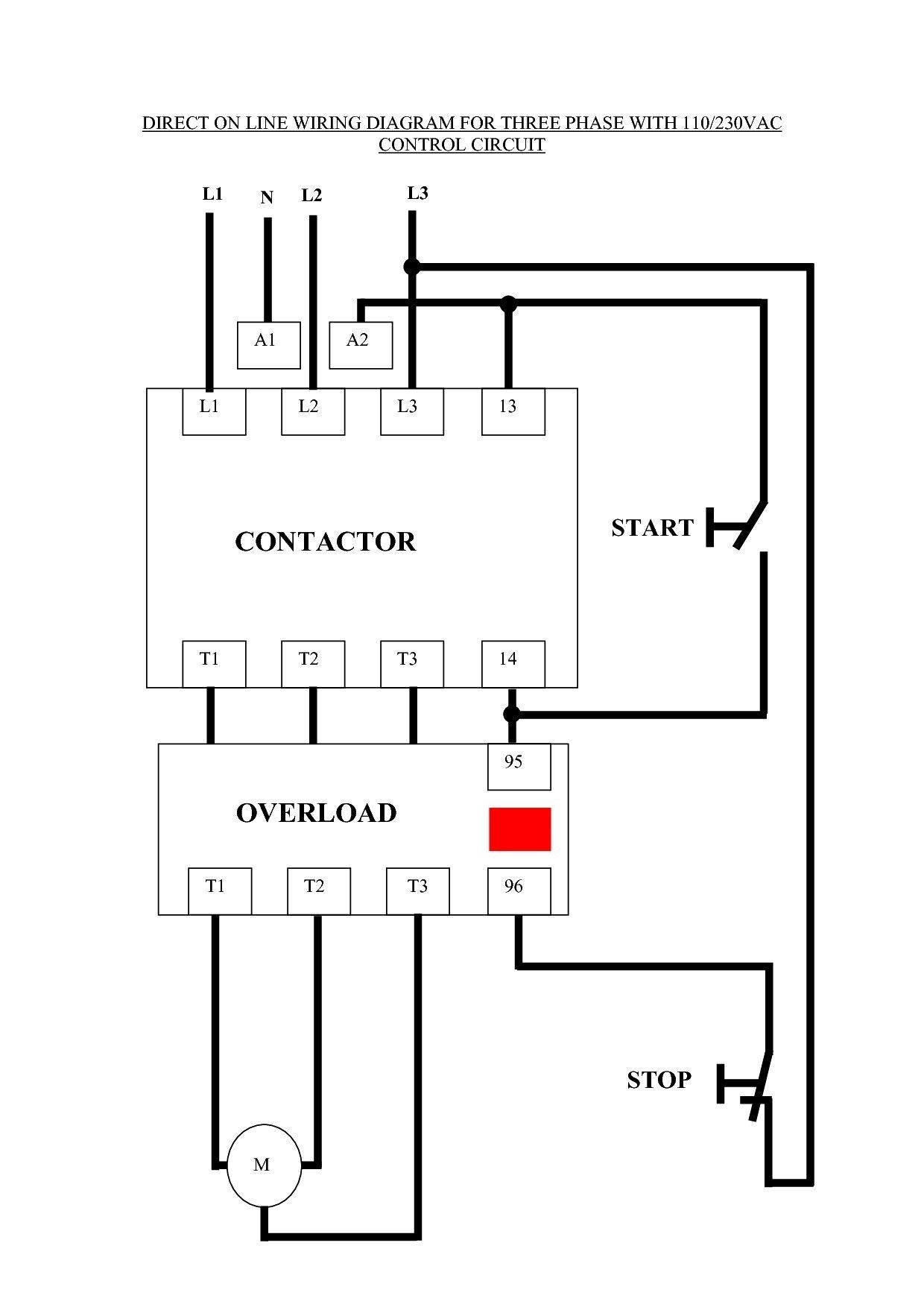
For example, in a typical three-phase AC contactor, there are three main terminals (L1, L2, L3) for connecting the power supply, three terminals (T1, T2, T3) for connecting the motor, and two terminals (A1, A2) for connecting the contactor coil. Each of these terminals must be connected correctly to ensure that the contactor operates as intended.
Misidentifying or misconnecting terminals can lead to various issues, including contactor malfunction, motor damage, or even electrical hazards. Proper terminal identification helps prevent these problems by ensuring that each terminal is connected to the correct circuit or component.
In practice, terminal identification is often indicated by color coding, numerical labels, or other markings on the contactor housing. Electrical professionals use these markings to identify the function of each terminal and make the appropriate connections.
Understanding terminal identification is not only crucial for the safe and efficient installation of AC Contactors but also for troubleshooting and maintenance. By knowing the function of each terminal, electrical professionals can quickly identify and resolve any issues that may arise, minimizing downtime and ensuring the reliable operation of the contactor and the connected equipment.
Coil Connections
In the realm of AC Contactor Wiring, coil connections play a pivotal role in ensuring the reliable operation and control of the contactor. Proper energization of the contactor coil is essential for initiating and maintaining the contactor’s switching action.
-
Coil Voltage:
The contactor coil must be connected to an AC voltage source that matches its rated voltage and frequency. Using an incorrect voltage can damage the coil or lead to improper operation.
-
Coil Terminals:
Contactors have designated terminals for coil connections. These terminals are typically labeled with “A1” and “A2” or similar markings. Reversing the polarity of the coil connections can affect the contactor’s operation.
-
Control Circuit:
The contactor coil is energized through a control circuit, which includes a push button, limit switch, or other control device. The control circuit provides the necessary voltage and current to activate the coil.
-
Coil Suppression:
When the contactor coil is de-energized, it can generate a voltage spike that can damage other components. Coil suppression techniques, such as using diodes or RC snubbers, are employed to mitigate these voltage transients.
Understanding and implementing proper coil connections are crucial for the safe and efficient operation of AC Contactors. Miswiring or incorrect connections can lead to premature contactor failure, malfunctioning of the controlled circuit, or electrical hazards. By paying close attention to coil voltage, terminal identification, control circuit compatibility, and coil suppression, electrical professionals can ensure reliable and long-lasting performance of AC Contactor Wiring systems.
Contact Configuration
In the realm of AC Contactor Wiring, contact configuration plays a crucial role in determining the functionality and capabilities of the contactor. Contact configuration refers to the arrangement and types of contacts within the contactor, which define how the contactor connects and disconnects circuits.
The contact configuration of an AC contactor typically consists of two main types of contacts: power contacts and auxiliary contacts. Power contacts are responsible for handling the main power flow of the circuit, while auxiliary contacts are used for control and signaling purposes. The arrangement of these contacts, including their, orientation, and connection, determines the contactor’s switching capabilities and its suitability for different applications.
Understanding contact configuration is essential for selecting the appropriate contactor for a given application. For instance, a contactor with a higher number of power contacts can handle higher current loads, while a contactor with multiple auxiliary contacts provides more flexibility for control and interfacing with other devices. Proper contact configuration also ensures safe and reliable operation of the contactor, preventing arcing, contact welding, and other potential issues.
In real-world applications, contact configuration plays a critical role in various industries. For example, in motor control circuits, contactors with multiple power contacts are used to handle the high inrush currents of motors. In automation systems, contactors with auxiliary contacts are employed to provide feedback signals and interface with PLCs and other control devices. Understanding contact configuration enables electrical professionals to design and implement AC Contactor Wiring systems that meet the specific requirements of their applications, ensuring efficient and reliable operation.
Control Circuit
Within the realm of AC Contactor Wiring, the control circuit holds a critical position, acting as the lifeblood that energizes the contactor coil and initiates the switching action. The control circuit is the maestro that orchestrates the contactor’s operation, providing the electrical signal that triggers the coil to create a magnetic field, pulling in the contactor’s contacts and completing the circuit.
The relationship between the control circuit and AC Contactor Wiring is akin to a symphony, where the control circuit sets the tempo and the contactor responds with its harmonious switching. Without a properly designed and implemented control circuit, the contactor remains dormant, unable to fulfill its role in controlling high-power circuits. Real-life examples abound, from simple push-button circuits to complex control systems in industrial settings, all relying on the control circuit to bring the contactor to life.
Understanding the control circuit is not merely an academic pursuit; it empowers electrical professionals with the knowledge to troubleshoot and maintain AC Contactor Wiring systems effectively. By deciphering the control circuit’s behavior, they can diagnose issues swiftly, ensuring minimal downtime and maintaining optimal performance. The practical significance of this understanding extends to various industries, from manufacturing and energy distribution to transportation and construction, where AC Contactors play a vital role in controlling electrical systems.
In summary, the control circuit stands as a pivotal component of AC Contactor Wiring, orchestrating the contactor’s operation and enabling the control of high-power circuits. Its importance cannot be overstated, as it breathes life into the contactor and allows it to fulfill its intended purpose. Electrical professionals who master the intricacies of the control circuit gain a profound understanding of AC Contactor Wiring systems, empowering them to design, install, and maintain these systems with precision and efficiency.
Power Circuit
Within the realm of AC Contactor Wiring, the power circuit stands as a critical component, forming the very essence of the contactor’s function. The power circuit is the electrical pathway that the contactor controls, enabling the flow of high currents and voltages to connected devices or loads. This interplay between the power circuit and AC Contactor Wiring is akin to a conductor and an orchestrathe contactor acts as the conductor, orchestrating the flow of electrical energy through the power circuit.
The relationship between the power circuit and AC Contactor Wiring is one of cause and effect. The contactor’s primary purpose is to control the power circuit, interrupting or establishing the flow of electricity as per the demands of the control circuit. This control allows for efficient management of electrical power, enabling the operation of motors, lighting systems, and other high-power devices. Real-life examples abound in industrial settings, where contactors play a vital role in controlling machinery, conveyor systems, and manufacturing processes.
Understanding the power circuit is crucial for electrical professionals working with AC Contactor Wiring systems. This understanding empowers them to design and implement wiring configurations that meet the specific requirements of the connected loads, ensuring safe and reliable operation. It also enables effective troubleshooting and maintenance, as electrical professionals can trace the power flow through the circuit, identify potential issues, and swiftly resolve them.
In summary, the power circuit forms the heart of AC Contactor Wiring systems, providing the means to control and manage electrical power. Its importance cannot be overstated, as it allows contactors to fulfill their role as switches for high-power circuits. Electrical professionals who master the intricacies of the power circuit gain a profound understanding of AC Contactor Wiring systems, empowering them to design, install, and maintain these systems with precision and efficiency.
Safety Considerations
In the realm of AC Contactor Wiring, safety considerations take center stage, ensuring the well-being of personnel and the integrity of equipment. These considerations encompass a range of measures and practices that aim to prevent electrical accidents, protect against electrical hazards, and minimize the risk of damage to electrical systems and connected devices.
-
Proper Grounding:
Grounding provides a low-resistance path for fault currents, preventing dangerous voltage buildup on equipment enclosures and reducing the risk of electrical shock.
-
Arc Flash Mitigation:
Arc flashes are dangerous electrical explosions that can occur when high currents flow through air. Arc flash mitigation measures, such as arc flash relays and personal protective equipment (PPE), help minimize the risk of injury and damage.
-
Overcurrent Protection:
Overcurrent protection devices, such as fuses and circuit breakers, prevent excessive currents from flowing through circuits, protecting wiring, components, and equipment from damage.
-
Guarding and Enclosure:
Guarding and enclosure prevent accidental contact with live parts, reducing the risk of electrical shock and injury. Enclosures also protect contactors and other components from environmental factors.
Adhering to safety considerations is paramount for the safe and reliable operation of AC Contactor Wiring systems. By implementing proper grounding, mitigating arc flash hazards, providing overcurrent protection, and employing guarding and enclosure, electrical professionals can create and maintain electrical systems that prioritize the safety of personnel and equipment.
Maintenance Best Practices
Maintenance best practices play a crucial role in ensuring the reliable operation and extended lifespan of AC Contactor Wiring systems. Regular inspection and upkeep help identify potential issues, prevent failures, and maintain optimal performance.
-
Visual Inspection:
Regular visual inspections involve checking for loose connections, damaged insulation, corrosion, and any other visible signs of wear or deterioration. This proactive approach helps detect potential problems early on, allowing for timely corrective actions.
-
Contact Maintenance:
Maintaining contactor contacts is essential to ensure proper electrical connections. This includes cleaning contacts to remove any dirt or oxidation, checking for pitting or excessive wear, and adjusting contact pressure if necessary.
-
Coil Inspection:
Inspecting the contactor coil involves checking for signs of overheating, insulation damage, or loose connections. A faulty coil can lead to contactor failure or erratic operation, making regular inspection crucial.
-
Lubrication:
Lubricating moving parts, such as the armature and bearings, helps reduce friction and wear. Proper lubrication ensures smooth operation, extends component life, and minimizes the risk of mechanical failures.
Implementing these maintenance best practices is essential for the long-term reliability and safety of AC Contactor Wiring systems. Regular inspections and upkeep can prevent costly failures, minimize downtime, and ensure that contactors operate safely and efficiently throughout their service life.
Troubleshooting Techniques
In the realm of AC Contactor Wiring, troubleshooting techniques take on paramount importance, forming the cornerstone of reliable and efficient system operation. These techniques empower electrical professionals with the ability to identify and resolve common issues, minimizing downtime and ensuring the smooth functioning of AC Contactor Wiring systems.
The relationship between troubleshooting techniques and AC Contactor Wiring is one of cause and effect. Without proper troubleshooting, minor issues can escalate into major problems, potentially leading to costly repairs or even dangerous situations. Real-life examples abound, such as loose connections causing overheating and potential electrical fires, or faulty coils leading to contactor failure and disruption of critical processes.
Understanding and applying troubleshooting techniques is a critical component of AC Contactor Wiring expertise. By utilizing these techniques, electrical professionals can systematically identify the root cause of issues, ranging from simple wiring errors to more complex contactor malfunctions. This understanding enables them to implement targeted solutions that restore system functionality and prevent future occurrences.
The practical applications of troubleshooting techniques extend across various industries and sectors. In manufacturing, for instance, timely troubleshooting can minimize production downtime and prevent costly losses. Similarly, in healthcare facilities, prompt resolution of contactor wiring issues ensures the uninterrupted operation of critical medical equipment. By mastering these techniques, electrical professionals become indispensable partners in maintaining the safety, reliability, and efficiency of AC Contactor Wiring systems.
Advanced Techniques
Within the realm of AC Contactor Wiring, advanced techniques emerge as a crucial aspect, empowering electrical professionals to navigate complex wiring configurations and achieve optimal system performance. These techniques extend beyond basic wiring practices, delving into intricate arrangements and specialized applications.
-
Multi-contactor Control:
Involving the coordination of multiple contactors to control a single load or multiple loads simultaneously, this technique enhances system flexibility and optimizes load management.
-
PLC-Based Control:
Leveraging programmable logic controllers (PLCs) to control contactor operation, this technique enables advanced logic and sequencing, providing greater control and automation capabilities.
-
Contactor Interlocking:
Employing interlocks between contactors to prevent simultaneous energization or ensure a specific sequence of operation, this technique enhances safety and system reliability.
-
Complex Circuit Design:
Encompassing the design and implementation of intricate control circuits involving multiple contactors, timers, and other components, this technique caters to specialized applications and demanding requirements.
Advanced techniques in AC Contactor Wiring empower electrical professionals to address complex system requirements, enhance operational efficiency, and achieve greater control and flexibility. These techniques find applications in diverse industries, from manufacturing and automation to power distribution and renewable energy systems, where reliable and efficient contactor wiring is paramount.


Related Posts


