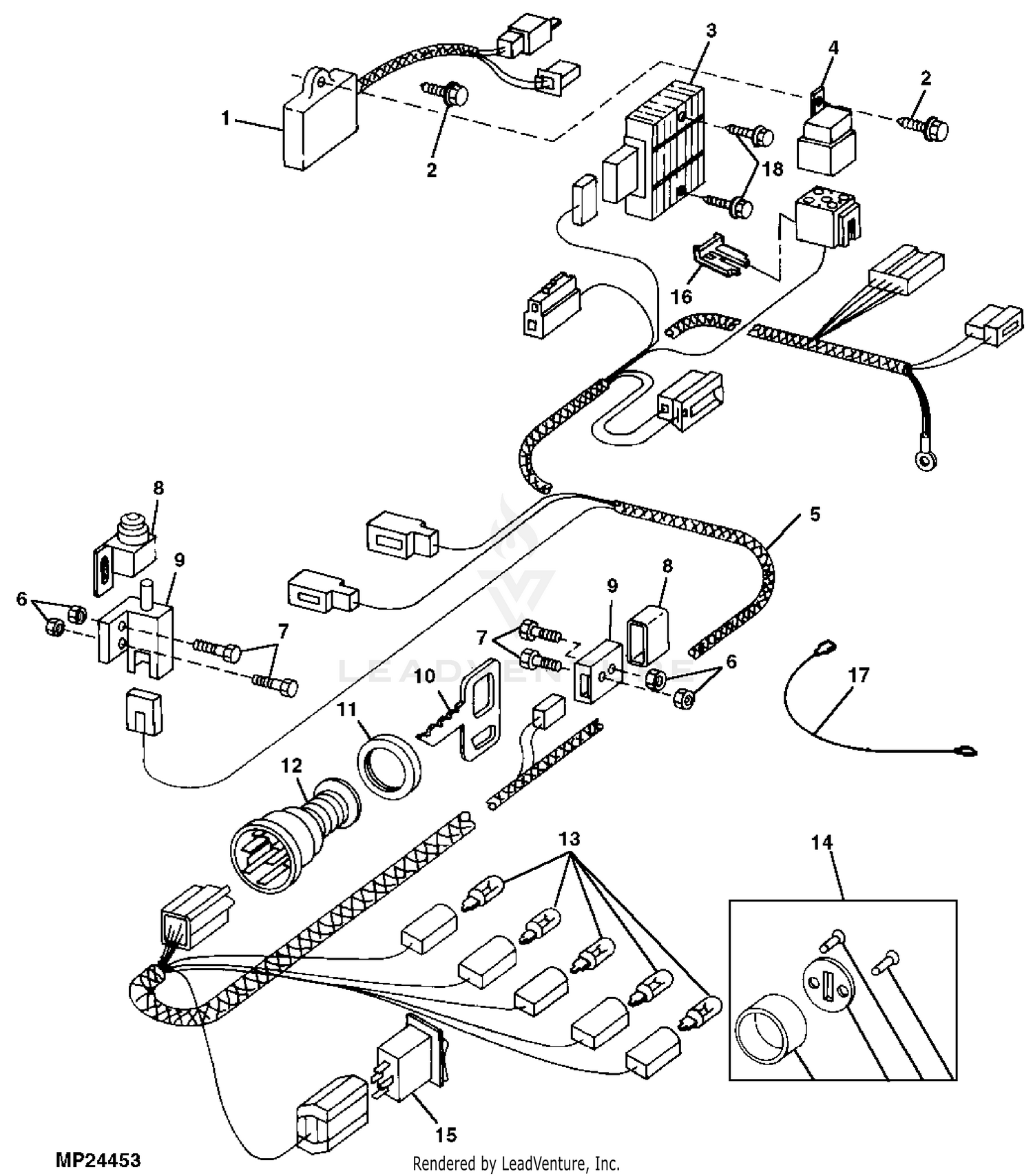
A John Deere Gator Wiring Diagram is a detailed schematic representation of the electrical system present in a John Deere Gator utility vehicle. It outlines the connections between various electrical components, including the battery, starter, alternator, lights, switches, and sensors. This diagram serves as a visual guide for troubleshooting electrical issues, facilitating repairs and maintenance tasks.
Wiring diagrams are instrumental in understanding the functioning and troubleshooting electrical systems. With their help, technicians can quickly identify and locate faulty components, reducing downtime and ensuring efficient repairs. They are also valuable for customizing electrical systems, adding accessories, or integrating new features into the vehicle.
John Deere Gator Wiring Diagrams have evolved over time, incorporating technological advancements and changes in vehicle designs. Modern diagrams often include detailed color-coding, making it easier to trace and identify specific circuits. The availability of digital wiring diagrams has also enhanced accessibility and convenience.
Understanding the key aspects of John Deere Gator Wiring Diagrams is paramount for effective electrical system maintenance and troubleshooting. These diagrams provide a comprehensive overview of the electrical connections within the vehicle, enabling technicians to identify and resolve issues efficiently.
- Accuracy: Wiring diagrams are meticulously crafted to accurately reflect the electrical system’s design and layout.
- Comprehensiveness: They encompass all electrical components, including wiring harnesses, connectors, and sensors.
- Color-coding: Modern diagrams often utilize color-coding to simplify circuit tracing and identification.
- Standardization: Wiring diagrams adhere to industry standards, ensuring consistency across different models and years.
- Troubleshooting: They serve as an invaluable tool for troubleshooting electrical problems, guiding technicians to faulty components.
- Customization: Wiring diagrams facilitate customization and integration of additional electrical features or accessories.
- Safety: Accurate wiring diagrams promote safe electrical system maintenance and repairs, preventing potential hazards.
- Time-saving: By providing a clear visual representation, wiring diagrams save time during electrical diagnostics and repairs.
- Accessibility: Digital wiring diagrams offer convenient access and portability, allowing technicians to work anywhere.
- Historical context: Wiring diagrams have evolved over time, reflecting technological advancements in vehicle electrical systems.
These aspects collectively contribute to the significance of John Deere Gator Wiring Diagrams, making them indispensable for maintaining and repairing the electrical systems of these utility vehicles. By understanding and utilizing these diagrams effectively, technicians can ensure the optimal performance and safety of John Deere Gators.
Accuracy
Accuracy is paramount in John Deere Gator Wiring Diagrams, as they serve as the foundation for understanding and troubleshooting the vehicle’s electrical system. Precise and detailed diagrams ensure that technicians can rely on them to make informed decisions and perform repairs confidently.
For instance, when troubleshooting an electrical issue, an accurate wiring diagram allows technicians to pinpoint the exact location of a faulty component, saving time and preventing unnecessary part replacements. This accuracy is crucial for efficient maintenance and repair, minimizing downtime and ensuring the Gator’s optimal performance.
Furthermore, accurate wiring diagrams facilitate modifications and upgrades to the electrical system. Whether adding accessories or integrating new features, technicians can use the diagram as a roadmap to ensure proper connections and avoid potential hazards. This understanding empowers them to customize the Gator’s electrical system to meet specific requirements.
In summary, the accuracy of John Deere Gator Wiring Diagrams is a cornerstone of their effectiveness. It enables technicians to troubleshoot issues efficiently, perform reliable repairs, and make informed modifications, ultimately contributing to the safety, performance, and longevity of the vehicle.
Comprehensiveness
The comprehensiveness of John Deere Gator Wiring Diagrams, encompassing all electrical components, wiring harnesses, connectors, and sensors, is a crucial aspect that contributes to their effectiveness in troubleshooting, repair, and customization.
By including every electrical component in the diagram, technicians gain a complete understanding of the Gator’s electrical system. This comprehensive view enables them to trace circuits, identify faulty components, and make informed decisions during repairs. For instance, if a headlight malfunctions, the wiring diagram provides a visual representation of the entire headlight circuit, including the power source, switches, and wiring harness. With this information, technicians can quickly pinpoint the issue, whether it’s a faulty bulb, a loose connection, or a break in the wiring.
Furthermore, the comprehensiveness of wiring diagrams is essential for customization and upgrades. When adding accessories or integrating new features, technicians can use the diagram to identify suitable connection points and ensure proper integration with the existing electrical system. This understanding helps prevent potential electrical hazards and ensures the reliable operation of added components.
In summary, the comprehensiveness of John Deere Gator Wiring Diagrams is a key factor in their effectiveness for troubleshooting, repair, and customization. By providing a complete representation of the electrical system, these diagrams empower technicians to make informed decisions, perform reliable repairs, and confidently modify the Gator’s electrical system to meet specific requirements.
Color-coding
Within the realm of John Deere Gator Wiring Diagrams, color-coding plays a pivotal role in enhancing the usability and effectiveness of these diagrams. By incorporating color-coding, technicians can navigate complex electrical systems with greater ease, leading to accurate troubleshooting and efficient repairs.
- Circuit Differentiation: Color-coding enables the clear identification of different circuits within the diagram. Each circuit is assigned a specific color, making it simple to trace the flow of electricity and locate specific components.
- Component Identification: Components such as fuses, relays, and sensors are often color-coded to match their corresponding circuits. This visual cue helps technicians quickly identify and locate components, saving time and reducing the risk of errors.
- Wiring Harness Tracing: Wiring harnesses, which bundle multiple wires together, can be color-coded to indicate their purpose or destination. This color-coding aids in tracing wires throughout the vehicle, facilitating repairs and modifications.
- International Standards: Color-coding often adheres to international standards, ensuring consistency across different models and manufacturers. This standardization simplifies troubleshooting and repairs for technicians familiar with industry practices.
In summary, the color-coding employed in John Deere Gator Wiring Diagrams enhances circuit differentiation, component identification, wiring harness tracing, and adherence to industry standards. As a result, technicians benefit from increased clarity, efficiency, and accuracy when troubleshooting and repairing the electrical systems of John Deere Gators.
Standardization
Within the realm of John Deere Gator Wiring Diagrams, standardization plays a vital role in enhancing their effectiveness and applicability across different models and years. By adhering to industry standards, these diagrams maintain a consistent structure and format, enabling technicians to easily navigate and interpret them regardless of their familiarity with specific Gator models.
This standardization ensures that the symbols, colors, and layout of John Deere Gator Wiring Diagrams are consistent, providing a common language for troubleshooting and repair. Technicians can transfer their knowledge and skills between different Gator models, reducing the learning curve and minimizing the risk of errors.
For instance, the color-coding of wires and components follows established industry standards, making it easier for technicians to identify and trace circuits across different models. The use of standardized symbols for electrical components, such as resistors, capacitors, and transistors, ensures consistent representation and understanding.
The practical applications of this standardization extend to real-life scenarios. When troubleshooting an electrical issue, technicians can confidently rely on the familiar layout and symbols of the wiring diagram, reducing diagnostic time and increasing accuracy. Additionally, when performing modifications or upgrades, technicians can seamlessly integrate new components into the electrical system, ensuring compatibility and proper functioning.
In summary, the adherence to industry standards in John Deere Gator Wiring Diagrams promotes consistency, simplifies troubleshooting, facilitates knowledge transfer, and enhances the overall effectiveness of electrical system maintenance and repair across different models and years.
Troubleshooting
Within the realm of John Deere Gator Wiring Diagrams, the aspect of troubleshooting holds paramount importance. These diagrams empower technicians with a roadmap to identify and resolve electrical issues efficiently, minimizing downtime and ensuring optimal vehicle performance.
- Circuit Tracing: Wiring diagrams provide a visual guide to trace electrical circuits, allowing technicians to pinpoint the exact location of faults. This eliminates guesswork and reduces the time spent on troubleshooting.
- Component Identification: Diagrams clearly illustrate the location and function of electrical components, enabling technicians to quickly identify faulty parts. This knowledge facilitates targeted repairs and prevents unnecessary component replacements.
- Voltage and Signal Analysis: Troubleshooting often involves measuring voltage and signals at various points in the electrical system. Wiring diagrams provide the necessary information to identify the correct test points, ensuring accurate diagnosis.
- Reference Values: Many wiring diagrams include reference values for voltage, resistance, and other parameters. These values serve as benchmarks for comparison, helping technicians determine if a component is functioning within its specified range.
The ability to troubleshoot electrical problems using John Deere Gator Wiring Diagrams has far-reaching implications. By reducing diagnostic time and facilitating targeted repairs, these diagrams contribute to increased uptime, lower maintenance costs, and enhanced safety. Furthermore, they empower technicians with the knowledge and confidence to resolve complex electrical issues, ensuring the reliable operation of John Deere Gators in various applications.
Customization
Within the realm of John Deere Gator Wiring Diagrams, customization plays a significant role in empowering owners and technicians to tailor the electrical system to meet specific requirements. These diagrams provide a roadmap for integrating additional electrical features or accessories, enhancing the functionality and versatility of the Gator.
- Accessory Integration: Wiring diagrams enable the seamless integration of accessories such as lights, winches, and audio systems. Technicians can identify suitable connection points and ensure proper wiring, ensuring optimal performance and safety.
- Feature Upgrades: Diagrams facilitate the upgrade of existing electrical features, such as replacing halogen headlights with LEDs or installing a backup camera. This customization enhances visibility, safety, and the overall user experience.
- Performance Modifications: For enthusiasts seeking improved performance, wiring diagrams provide guidance for modifications such as installing a high-output alternator or upgrading the ignition system. These modifications can enhance power, efficiency, and reliability.
- Custom Wiring: Wiring diagrams empower technicians to create custom wiring solutions for unique applications. Whether it’s adding a custom lighting setup or integrating specialized equipment, diagrams provide the necessary framework for safe and effective electrical installations.
The ability to customize John Deere Gators using wiring diagrams opens up a wide range of possibilities. From enhancing functionality to improving performance, these diagrams empower owners and technicians to tailor their Gators to specific needs and preferences. By providing a clear understanding of the electrical system, wiring diagrams play a pivotal role in unlocking the full potential and versatility of John Deere Gators.
Safety
In the realm of John Deere Gator Wiring Diagrams, the aspect of safety takes center stage. Accurate and comprehensive diagrams are not merely tools for troubleshooting and customization; they play a critical role in ensuring the safe maintenance and repair of electrical systems, mitigating potential hazards that could compromise the integrity and functionality of the Gator.
- Prevention of Electrical Fires: Electrical fires pose a significant risk in any vehicle, and faulty wiring is a leading cause. Accurate wiring diagrams guide technicians in identifying and correcting wiring errors, preventing short circuits and potential fires.
- Protection against Electrical Shock: Improper handling of electrical systems can result in electrical shock. Diagrams provide clear instructions on how to safely disconnect and reconnect components, minimizing the risk of accidental contact with live wires.
- Safeguarding Electrical Components: Electrical components are sensitive to overvoltage, incorrect polarity, and other electrical hazards. Wiring diagrams ensure that components are connected correctly, preventing damage and extending their lifespan.
- Compliance with Safety Standards: Wiring diagrams facilitate compliance with industry safety standards and regulations. By adhering to these standards, technicians ensure that electrical systems meet the required safety levels, mitigating risks and protecting users.
In conclusion, the safety aspect of John Deere Gator Wiring Diagrams cannot be overstated. Accurate and comprehensive diagrams are indispensable for safe electrical system maintenance and repairs, preventing potential hazards that could lead to electrical fires, shock, component damage, and non-compliance with safety standards. By empowering technicians with the knowledge and guidance to work safely on electrical systems, these diagrams contribute to the overall reliability, longevity, and safety of John Deere Gators.
Time-saving
In the realm of John Deere Gator Wiring Diagrams, the time-saving aspect holds paramount importance. These diagrams serve as invaluable tools that enable technicians to diagnose and repair electrical issues swiftly and efficiently, minimizing downtime and maximizing productivity.
- Rapid Fault Identification: Wiring diagrams provide a clear visual representation of the entire electrical system, allowing technicians to quickly identify the root cause of electrical problems. By tracing circuits and analyzing component connections, they can pinpoint faulty components or loose connections, eliminating the need for extensive troubleshooting.
- Targeted Repairs: Once the faulty component or connection is identified, wiring diagrams guide technicians in performing targeted repairs. They provide precise instructions on how to safely disconnect, replace, or repair the affected components, minimizing the time spent on dismantling and reassembling the electrical system.
- Reduced Trial-and-Error: Troubleshooting electrical issues often involves trial-and-error methods, which can be time-consuming and potentially lead to further problems. Wiring diagrams eliminate guesswork by providing a clear roadmap of the electrical system, enabling technicians to make informed decisions and avoid unnecessary part replacements or repairs.
- Enhanced Efficiency: The overall efficiency of electrical repairs is significantly improved with the use of wiring diagrams. By streamlining the diagnostic and repair process, technicians can resolve issues faster, allowing them to attend to other maintenance tasks or get the Gator back in operation with minimal downtime.
In conclusion, the time-saving aspect of John Deere Gator Wiring Diagrams is a critical factor in maintaining the optimal performance and productivity of these machines. By providing a clear visual representation of the electrical system, these diagrams empower technicians to diagnose and repair electrical issues quickly and efficiently, minimizing downtime and maximizing the uptime of John Deere Gators.
Accessibility
In the realm of John Deere Gator Wiring Diagrams, accessibility assumes paramount importance in today’s digital age. Digital wiring diagrams offer unprecedented convenience and portability, empowering technicians to work efficiently and effectively in various settings, both in the workshop and in the field.
- Offline Access: Digital wiring diagrams can be stored on laptops, tablets, or smartphones, providing technicians with instant access to critical electrical information even in remote locations where internet connectivity may be limited or unavailable.
- Portability and Convenience: Unlike traditional paper diagrams, digital diagrams are highly portable and can be easily carried around, allowing technicians to troubleshoot and repair electrical issues on the go. This portability is especially advantageous when working on Gators in remote areas or during field service calls.
- Real-Time Updates: Digital wiring diagrams can be updated in real-time by manufacturers, ensuring that technicians always have access to the most current and accurate information. This eliminates the need to manually update paper diagrams, reducing the risk of errors and ensuring that repairs are performed according to the latest specifications.
- Collaboration and Sharing: Digital wiring diagrams facilitate collaboration among technicians, allowing them to share and discuss electrical issues and solutions remotely. This collaborative approach can expedite troubleshooting and repairs, especially when working on complex electrical systems or diagnosing intermittent problems.
The accessibility provided by digital wiring diagrams has revolutionized the way technicians maintain and repair John Deere Gators. By offering convenient access, portability, real-time updates, and enhanced collaboration, digital diagrams have become indispensable tools for ensuring the optimal performance and reliability of Gators in diverse operating environments.
Historical context
The historical evolution of wiring diagrams stands as a testament to the dynamic relationship between technological advancements and the design and complexity of vehicle electrical systems. As technology progressed, so too did the need for more sophisticated and detailed wiring diagrams to accurately represent and guide the maintenance and repair of these systems.
John Deere Gator Wiring Diagrams are a prime example of this evolution. Over the years, Gator electrical systems have grown increasingly complex, incorporating advanced features such as fuel injection, electronic controls, and computerized diagnostics. This increased complexity necessitated the development of more comprehensive and user-friendly wiring diagrams to support technicians in troubleshooting and repairing these systems effectively.
The historical context of wiring diagrams provides valuable insights into the design and functionality of John Deere Gator electrical systems. By understanding the evolution of these diagrams, technicians can better appreciate the complexities involved in modern electrical systems and the importance of accurate and up-to-date wiring information.
Furthermore, the historical context highlights the ongoing need for continuous learning and professional development among technicians. As technology advances and vehicle electrical systems become even more sophisticated, it is crucial for technicians to stay abreast of the latest wiring diagram conventions and industry best practices to ensure they possess the knowledge and skills to maintain and repair these systems effectively.
![]()


Related Posts


