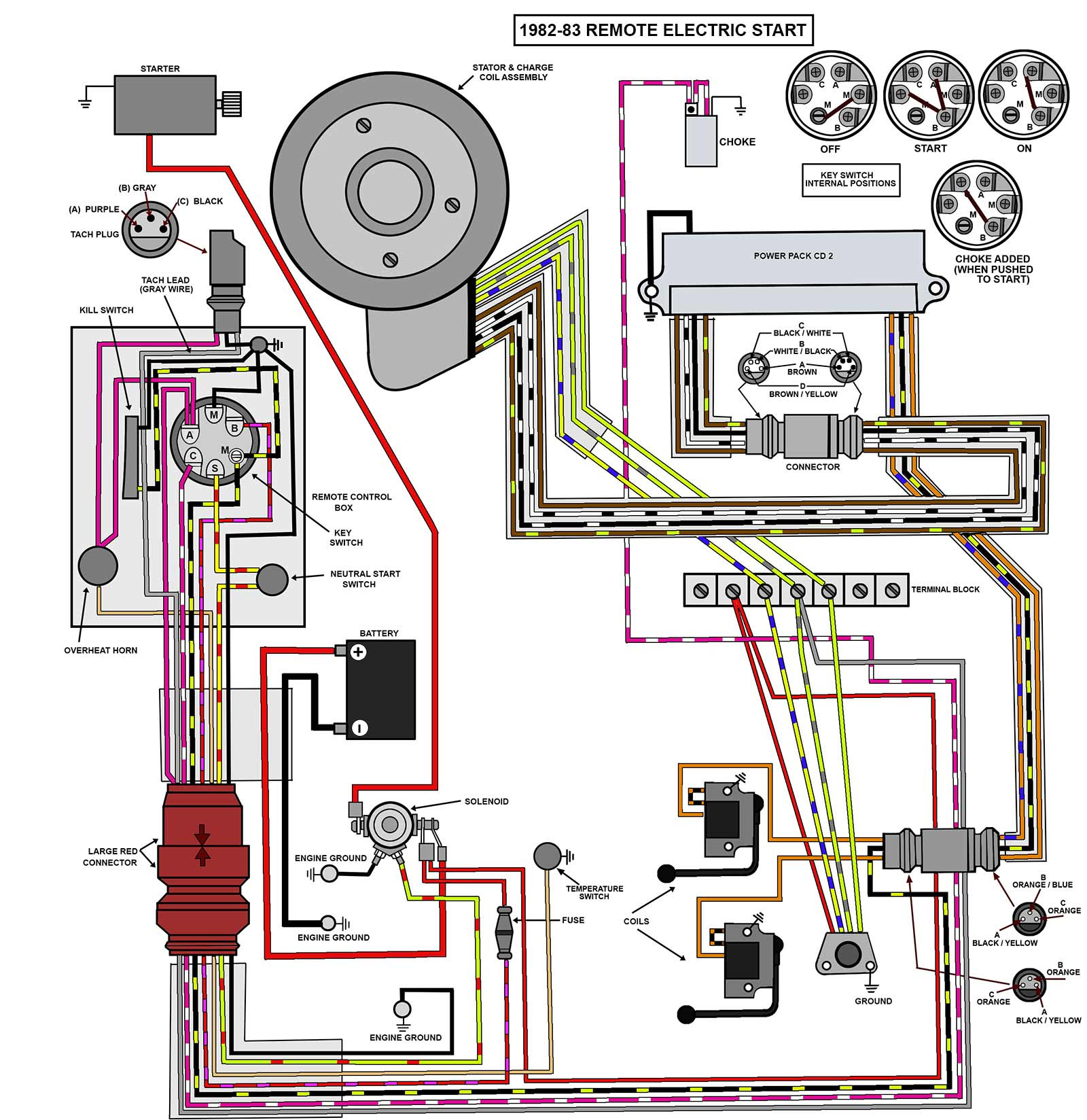
An outboard motor Evinrude ignition switch wiring diagram is a technical document that illustrates the electrical connections and components of the ignition system in an Evinrude outboard motor. It provides a visual representation of the wiring, switches, and other electrical elements involved in starting and running the engine.
The ignition switch is a crucial component in the outboard motor’s electrical system. It controls the flow of electricity to the ignition coil, which generates the spark necessary for combustion. The wiring diagram shows how the ignition switch is connected to the battery, starter solenoid, ignition coil, and other components, ensuring proper electrical flow for engine operation.
Understanding the outboard motor Evinrude ignition switch wiring diagram is essential for troubleshooting and repairing electrical issues in the engine’s ignition system. It helps mechanics and boat owners identify and trace electrical connections, diagnose faulty components, and ensure safe and reliable operation of the outboard motor.
Understanding the essential aspects of an outboard motor Evinrude ignition switch wiring diagram is crucial for diagnosing and resolving electrical issues, ensuring the safe and reliable operation of the outboard motor. Here are ten key aspects to consider:
- Circuit Components: Identifying the various electrical components (battery, ignition switch, starter solenoid, ignition coil, etc.) in the ignition system.
- Wiring Connections: Tracing the electrical connections between the components, including wire colors and terminal locations.
- Ignition Switch Function: Understanding the role of the ignition switch in controlling the flow of electricity to the ignition system.
- Starter Solenoid Operation: Describing the function of the starter solenoid in engaging the starter motor.
- Ignition Coil Function: Explaining how the ignition coil generates the high-voltage spark for combustion.
- Troubleshooting Techniques: Outlining methods for diagnosing common electrical faults using the wiring diagram.
- Safety Precautions: Emphasizing the importance of following safety guidelines when working on electrical systems.
- Compatibility Considerations: Ensuring that the wiring diagram matches the specific model and year of the outboard motor.
- Reference for Repair: Utilizing the wiring diagram as a guide for repairing and replacing faulty components.
- Performance Optimization: Verifying correct electrical connections to ensure optimal engine performance.
In conclusion, a thorough understanding of the outboard motor Evinrude ignition switch wiring diagram enables boat owners and mechanics to maintain and troubleshoot the electrical system effectively. By comprehending the circuit components, wiring connections, and the functions of each component, individuals can diagnose and resolve issues, ensuring the reliable operation of their outboard motor.
Circuit Components
Understanding the circuit components involved in an outboard motor Evinrude ignition switch wiring diagram is crucial for effective troubleshooting and repair. By identifying the various electrical components and their functions, individuals can gain a deeper understanding of the ignition system, its operation, and potential issues.
- Battery: The battery serves as the primary power source for the ignition system, providing the electrical energy required for starting and running the engine.
- Ignition Switch: The ignition switch controls the flow of electricity to the ignition system. When turned to the “on” position, it completes the circuit, allowing current to flow to the other components.
- Starter Solenoid: The starter solenoid is an electromagnetic switch that engages the starter motor when the ignition switch is turned to the “start” position.
- Ignition Coil: The ignition coil is a transformer that converts the low-voltage current from the battery into a high-voltage spark, which is then delivered to the spark plugs.
Comprehending the functions and interconnections of these circuit components empowers individuals to diagnose and resolve electrical issues in the ignition system. By tracing the flow of electricity through the wiring diagram and identifying faulty components, they can ensure the reliable operation of their outboard motor.
Wiring Connections
Wiring connections form the backbone of an outboard motor Evinrude ignition switch wiring diagram, providing the physical pathways for electricity to flow between the various components of the ignition system. Understanding these connections, including wire colors and terminal locations, is paramount for effective troubleshooting and repair.
- Color-Coded Wires: Wires in an ignition system are typically color-coded to facilitate identification and tracing. Each color corresponds to a specific function or component, such as red for positive power, black for ground, and blue for ignition.
- Terminal Locations: Terminals are connection points where wires are attached to components. Wiring diagrams indicate the specific terminal locations for each component, ensuring proper connections and avoiding short circuits.
- Grounding Points: Grounding points provide a reference point for the electrical system, ensuring that excess voltage is safely discharged. Wiring diagrams specify the designated grounding points for the ignition system.
- Connector Types: Various types of connectors are used in ignition systems, such as bullet connectors, spade terminals, and ring terminals. Wiring diagrams illustrate the specific connector types used and their locations.
Comprehending the wiring connections of an outboard motor Evinrude ignition switch wiring diagram empowers individuals to trace electrical faults, identify damaged wires, and ensure proper connections. By following the color-coded wires and understanding the terminal locations, they can diagnose and resolve ignition system issues, ensuring the reliable operation of their outboard motor.
Ignition Switch Function
In the context of an outboard motor Evinrude ignition switch wiring diagram, the ignition switch plays a critical role in controlling the flow of electricity to the ignition system. Understanding its function is essential for diagnosing and resolving electrical issues, ensuring the reliable operation of the outboard motor.
- Circuit Completion: The ignition switch completes the electrical circuit between the battery and the ignition system. When turned to the “on” position, it allows current to flow, powering the ignition coil, starter solenoid, and other components.
- Multiple Positions: Ignition switches typically have multiple positions, including “off,” “on,” “start,” and “accessory.” Each position controls the flow of electricity to different components, enabling functions such as starting the engine, operating accessories, and turning off the ignition system.
- Safety Feature: The ignition switch acts as a safety feature by preventing accidental starting of the engine. Keyed ignition switches require a key to be inserted and turned to the “start” position, reducing the risk of unintended engine engagement.
- Troubleshooting Aid: By understanding the function of the ignition switch and its position in the wiring diagram, individuals can effectively troubleshoot electrical issues related to starting and ignition. Identifying a faulty ignition switch or loose connections can help resolve problems and restore proper engine operation.
Comprehending the ignition switch function within the outboard motor Evinrude ignition switch wiring diagram empowers individuals to maintain and repair their outboard motor’s ignition system with confidence. By grasping the role of the ignition switch in controlling the flow of electricity, they can diagnose and resolve electrical faults, ensuring the reliable performance of their outboard motor.
Starter Solenoid Operation
Within the context of an Outboard Motor Evinrude Ignition Switch Wiring Diagram, the starter solenoid plays a crucial role in the starting process of the engine. Understanding its operation is essential for troubleshooting and resolving ignition-related issues.
- Solenoid Function: The starter solenoid acts as a switch that engages the starter motor. When the ignition switch is turned to the “start” position, it sends a signal to the solenoid, which in turn completes the electrical circuit between the battery and the starter motor.
- Plunger Mechanism: The solenoid consists of a coil and a plunger. When energized, the coil creates a magnetic field that pulls the plunger into the solenoid, engaging the starter motor’s Bendix gear with the engine’s flywheel.
- Electrical Connections: The starter solenoid requires proper electrical connections to function effectively. Loose or corroded connections can prevent the solenoid from engaging the starter motor, resulting in starting problems.
- Troubleshooting: If the outboard motor fails to start, the starter solenoid may be faulty or its connections may need to be inspected. Testing the solenoid’s continuity and checking for loose connections can help identify the source of the problem.
Comprehending the starter solenoid operation and its role in the ignition switch wiring diagram equips individuals with the knowledge to diagnose and resolve starting issues in their outboard motor. By understanding the function of the solenoid and its electrical connections, they can ensure the reliable starting and operation of their outboard motor.
Ignition Coil Function
Within an Outboard Motor Evinrude Ignition Switch Wiring Diagram, the ignition coil holds a critical position, transforming low-voltage electrical energy into the high-voltage spark necessary for combustion. Comprehending the function of the ignition coil is fundamental to understanding the ignition system and diagnosing potential issues.
The ignition coil operates on the principle of electromagnetic induction, where a rapidly changing magnetic field induces an electrical current in a nearby conductor. In the ignition system, the primary winding of the ignition coil is connected to the battery, while the secondary winding is connected to the spark plugs. When the ignition switch is turned on, current flows through the primary winding, creating a strong magnetic field. This magnetic field then collapses rapidly as the current is interrupted, inducing a high-voltage pulse in the secondary winding.
The high-voltage pulse travels through the secondary winding to the spark plugs, where it jumps the gap between the electrodes, creating a spark that ignites the air-fuel mixture in the engine’s cylinders. This process occurs repeatedly, providing the timed ignition necessary for smooth engine operation.
Understanding the ignition coil function and its connection to the Outboard Motor Evinrude Ignition Switch Wiring Diagram empowers individuals to troubleshoot and resolve ignition-related problems. By verifying proper electrical connections, testing the ignition coil’s resistance, and ensuring the spark plugs are in good condition, outboard motor owners can maintain optimal engine performance and reliable operation.
Troubleshooting Techniques
Troubleshooting techniques, coupled with an Outboard Motor Evinrude Ignition Switch Wiring Diagram, provide a comprehensive approach to diagnosing and resolving electrical faults within the ignition system. The wiring diagram serves as a roadmap, guiding individuals in tracing electrical connections and identifying potential issues.
Common electrical faults in outboard motor ignition systems include:
- Loose or corroded connections
- Faulty ignition switch
- Malfunctioning starter solenoid
- Defective ignition coil
- Damaged spark plugs
Using the wiring diagram, individuals can systematically check each component and connection, utilizing multimeters and other diagnostic tools to pinpoint the source of the fault. For instance, if the engine fails to start, the wiring diagram can help trace the electrical path from the battery to the starter motor, enabling the identification of a faulty starter solenoid or loose connection.
Troubleshooting electrical faults using the wiring diagram requires a methodical approach and a thorough understanding of the ignition system’s components and their interconnections. By following the wiring diagram and employing appropriate troubleshooting techniques, outboard motor owners can effectively diagnose and resolve electrical issues, ensuring the reliable operation of their engines.
Safety Precautions
When working on electrical systems, particularly those related to outboard motors, adhering to safety precautions is paramount. The Outboard Motor Evinrude Ignition Switch Wiring Diagram provides a comprehensive guide to the electrical connections and components, but it is crucial to prioritize safety throughout the process.
- Electrical Hazards: Electrical systems carry significant voltage, posing the risk of electrical shock or electrocution. Ensure that the power is disconnected and all capacitors are discharged before handling any electrical components.
- Proper Tools: Utilize insulated tools designed for electrical work to minimize the risk of accidental contact or short circuits. Avoid using metal tools that could conduct electricity.
- Protective Gear: Wear appropriate protective gear, such as rubber gloves and safety glasses, to safeguard against potential electrical hazards. These measures can prevent injuries in the event of an electrical fault or accidental contact.
By following these safety precautions and referencing the Outboard Motor Evinrude Ignition Switch Wiring Diagram, individuals can approach electrical work with confidence, minimizing the risks associated with electrical systems and ensuring a safe and successful repair or maintenance process.
Compatibility Considerations
Within the context of “Outboard Motor Evinrude Ignition Switch Wiring Diagram,” compatibility considerations hold paramount importance. Ensuring that the wiring diagram aligns precisely with the specific model and year of the outboard motor is vital for several reasons:
- Component Compatibility: Different outboard motor models and years may incorporate unique electrical components, such as ignition coils, starter solenoids, and sensors. A mismatched wiring diagram could lead to incorrect connections and potential damage to these components.
- Electrical System Variations: The electrical system architecture can vary across outboard motor models and years. Wiring diagrams specific to the exact model and year ensure compatibility with the boat’s electrical system, preventing issues such as overloads or undervoltages.
- Safety Implications: Using an incorrect wiring diagram can compromise the safety of the outboard motor and its occupants. Proper wiring ensures that electrical components function as intended, minimizing the risk of electrical fires or malfunctions.
- Performance Optimization: A compatible wiring diagram optimizes the performance of the outboard motor. Correct electrical connections ensure efficient power distribution, leading to optimal ignition timing, fuel injection, and overall engine performance.
By adhering to compatibility considerations and utilizing the correct wiring diagram specific to the outboard motor’s model and year, individuals can ensure safe, reliable, and high-performing operation of their outboard motor.
Reference for Repair
Within the context of “Outboard Motor Evinrude Ignition Switch Wiring Diagram,” the aspect of “Reference for Repair” plays a pivotal role. The wiring diagram serves as an indispensable guide for repairing and replacing faulty components, enabling individuals to troubleshoot and resolve electrical issues effectively.
The wiring diagram provides a comprehensive overview of the electrical system, including the ignition switch, starter solenoid, ignition coil, and other critical components. By referring to the diagram, mechanics and boat owners can trace electrical connections, identify faulty components, and determine the appropriate repair or replacement actions.
For instance, if an outboard motor experiences ignition problems, the wiring diagram can help pinpoint the issue to a faulty ignition coil or a loose connection in the ignition switch circuit. The diagram guides the repair process, indicating the specific steps and precautions necessary for safe and effective repairs.
Furthermore, the wiring diagram empowers individuals to make informed decisions regarding component replacement. By identifying the exact specifications and compatibility requirements of the faulty component, the diagram ensures that the replacement part is appropriate for the specific outboard motor model and year.
In summary, the “Reference for Repair” aspect of the “Outboard Motor Evinrude Ignition Switch Wiring Diagram” is crucial for troubleshooting, repairing, and replacing faulty components. The wiring diagram provides a visual representation of the electrical system, enabling individuals to accurately diagnose issues, select the appropriate replacement parts, and perform repairs with precision and confidence.
Performance Optimization
Within the context of “Outboard Motor Evinrude Ignition Switch Wiring Diagram,” the aspect of “Performance Optimization: Verifying correct electrical connections to ensure optimal engine performance” holds critical importance. The accuracy of electrical connections directly influences the efficiency and reliability of the outboard motor’s operation, impacting factors such as ignition timing, fuel injection, and overall engine performance.
- Ignition Timing Precision: Precise electrical connections ensure that the ignition timing is properly aligned, resulting in optimal combustion within the engine cylinders. Incorrect timing can lead to reduced power output, increased fuel consumption, and potential engine damage.
- Efficient Fuel Injection: Correct electrical connections to fuel injectors enable precise fuel delivery, optimizing the air-fuel mixture for efficient combustion. Improper connections can disrupt the fuel injection process, leading to engine performance issues and increased emissions.
- Reliable Electrical System: Ensuring correct electrical connections minimizes the risk of electrical faults and malfunctions. Loose or faulty connections can cause intermittent operation, starting problems, or even electrical fires. Proper connections enhance the reliability and safety of the outboard motor’s electrical system.
- Extended Engine Life: Optimal engine performance, facilitated by correct electrical connections, contributes to reduced wear and tear on engine components. Proper electrical connections promote efficient operation, reducing the likelihood of premature breakdowns and extending the overall lifespan of the outboard motor.
Verifying and maintaining correct electrical connections is a crucial aspect of outboard motor maintenance. By adhering to the guidelines provided in the “Outboard Motor Evinrude Ignition Switch Wiring Diagram,” boat owners and mechanics can ensure optimal engine performance, reliability, and longevity.


Related Posts


