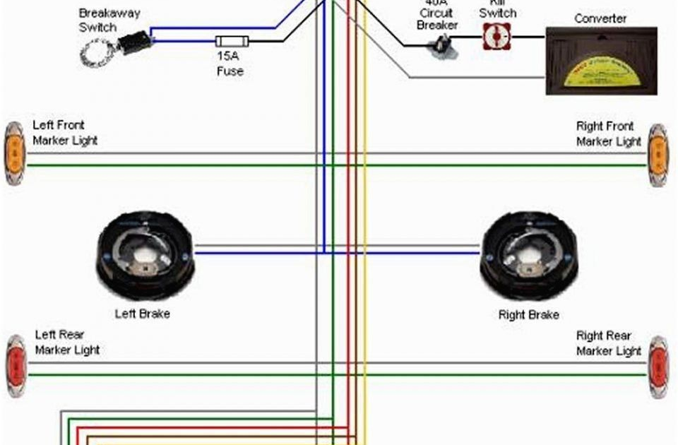
A 7-Pin Trailer Brake Wiring Diagram is a plan that illustrates the electrical connections between a vehicle and an attached trailer, specifically focusing on the braking system. Each pin in the 7-pin connector serves a specific function:
- Ground
- Left turn signal
- Tail lights
- Right turn signal
- Brake lights
- Reverse lights
- Trailer brakes
Proper wiring is crucial to ensure the trailer’s brake lights, turn signals, and other critical functions work correctly. This diagram provides a standardized roadmap for connecting the electrical systems between the vehicle and the trailer, promoting safety and ensuring compliance with regulations.
With increasing traffic congestion and the need for efficient transportation systems, understanding trailer brake wiring diagrams has become more relevant than ever. They enable effective and safe towing practices, reducing risks and enhancing overall road safety.
Understanding the essential aspects of Trailer Brake Wiring Diagram 7 Pin is crucial for safe and efficient trailer towing practices. These aspects encompass the core components, functionality, and implications related to this vital system.
- Electrical Connections: The diagram outlines the specific electrical connections between the vehicle and the trailer, ensuring proper functioning of brake lights, turn signals, and other critical features.
- Safety Regulations: Adhering to the wiring diagram helps ensure compliance with safety regulations, promoting road safety and minimizing risks.
- Compatibility: The diagram guides the selection of compatible components, ensuring seamless integration between the vehicle and the trailer’s braking systems.
- Troubleshooting: A clear understanding of the wiring diagram aids in troubleshooting electrical faults, minimizing downtime and ensuring timely repairs.
- Maintenance: Regular inspection and maintenance of the wiring system, based on the diagram, helps prevent malfunctions and extends the lifespan of the components.
- Circuit Protection: The diagram incorporates circuit protection mechanisms, such as fuses or circuit breakers, to safeguard the electrical system from overloads and short circuits.
- Customization: The diagram can be customized to accommodate specific trailer configurations or additional features, ensuring versatility and adaptability.
- Standardization: The 7-pin connector is a standardized interface, enabling compatibility with various vehicles and trailers, simplifying connections and enhancing safety.
- Load Capacity: The wiring diagram takes into account the load capacity of the trailer, ensuring that the electrical system can handle the power requirements of the braking and other components.
These aspects collectively contribute to the safe and efficient operation of trailer brake systems. Proper understanding and implementation of the Trailer Brake Wiring Diagram 7 Pin are essential for responsible towing practices, reducing accidents, and enhancing overall road safety.
Electrical Connections
Within the context of a Trailer Brake Wiring Diagram 7 Pin, understanding the electrical connections is paramount for safe and reliable towing practices. This intricate network of wires and connectors ensures seamless communication between the vehicle and the attached trailer, enabling essential features such as brake lights, turn signals, and other critical functions to operate flawlessly.
- Wiring Harness: The wiring harness serves as the backbone of the electrical connections, carrying electrical signals between the vehicle and the trailer. It comprises a bundle of color-coded wires, each designated for a specific function, ensuring proper coordination.
- Connector Types: The 7-pin connector, a standardized interface, plays a crucial role in establishing the electrical connection between the vehicle and the trailer. This connector houses seven terminals, each corresponding to a specific function, ensuring secure and reliable signal transmission.
- Circuit Protection: Electrical circuits within the wiring system are protected by fuses or circuit breakers. These devices safeguard the system from overloads and short circuits, preventing damage to electrical components and potential hazards.
- Grounding: Proper grounding is essential for completing the electrical circuit. The grounding wire provides a path for electrical current to return to the vehicle’s chassis, ensuring the proper functioning of the electrical system.
The meticulous planning and precise execution of electrical connections in a Trailer Brake Wiring Diagram 7 Pin are indispensable for ensuring the safe and effective operation of trailer brake systems. By adhering to standardized wiring diagrams and employing proper installation techniques, individuals can minimize electrical faults, enhance safety, and enjoy a seamless towing experience.
Safety Regulations
Within the context of Trailer Brake Wiring Diagram 7 Pin, adhering to safety regulations is of paramount importance, as it directly impacts the safety and well-being of individuals on the road. By following standardized wiring diagrams and implementing proper installation techniques, individuals can minimize electrical faults, reduce the likelihood of accidents, and contribute to a safer driving environment.
- Legal Compliance: Adhering to safety regulations, as outlined in the wiring diagram, ensures compliance with legal requirements and standards established by regulatory bodies. This compliance helps avoid potential legal liabilities and penalties.
- TV Certification: In certain regions, such as the European Union, obtaining TV certification for trailer brake wiring systems is a recognized mark of safety and quality. TV certification involves rigorous testing and evaluation to ensure compliance with stringent safety standards.
- Insurance Coverage: Proper wiring and adherence to safety regulations can impact insurance coverage in the event of an accident. Insurance providers may consider compliance with safety standards when determining coverage and premiums.
- Accident Prevention: By ensuring proper electrical connections and functioning of trailer brake systems, adherence to safety regulations helps prevent accidents caused by electrical malfunctions, brake failures, or other wiring-related issues.
Understanding and implementing the safety regulations outlined in the Trailer Brake Wiring Diagram 7 Pin is a shared responsibility among manufacturers, installers, and users. By working together to ensure compliance, we can create a safer environment for everyone on the road.
Compatibility
Within the context of Trailer Brake Wiring Diagram 7 Pin, compatibility plays a pivotal role in ensuring seamless integration and safe operation of the braking system between the towing vehicle and the attached trailer. The diagram serves as a guide for selecting compatible components that meet specific electrical and performance requirements, ensuring proper functionality and adherence to safety standards.
Electrical compatibility is critical to avoid mismatches between the vehicle’s electrical system and the trailer’s braking system. The diagram specifies the electrical characteristics, such as voltage, amperage, and pin assignments, to ensure that the components can communicate effectively and operate in harmony. By selecting compatible components, potential electrical faults, malfunctions, or damage to the system can be minimized.
For instance, using incompatible brake controllers, which regulate the trailer’s brakes, can lead to improper braking performance. The diagram provides guidance on choosing a brake controller that is compatible with both the vehicle’s electrical system and the trailer’s braking system, ensuring optimal braking response and preventing potential safety hazards.
Moreover, the diagram helps ensure mechanical compatibility between the vehicle’s towing system and the trailer’s brake components. It specifies the physical dimensions, mounting points, and connection types to ensure proper fitment and secure attachment. This compatibility ensures that the braking system can be installed correctly, preventing issues such as loose connections, misaligned components, or interference with other parts.
Understanding the importance of compatibility and following the Trailer Brake Wiring Diagram 7 Pin allows for the selection of appropriate components and proper installation, resulting in a reliable and safe braking system for towing applications.
Troubleshooting
Within the context of “Trailer Brake Wiring Diagram 7 Pin,” troubleshooting plays a crucial role in maintaining a reliable and functional braking system for towing applications. A clear understanding of the wiring diagram empowers individuals to identify and resolve electrical faults efficiently, minimizing downtime and ensuring timely repairs.
The Trailer Brake Wiring Diagram 7 Pin provides a comprehensive roadmap for the electrical connections between the towing vehicle and the trailer. It outlines the specific functions of each wire and terminal within the 7-pin connector, enabling users to trace electrical signals and pinpoint potential issues.
For instance, if the trailer’s brake lights are malfunctioning, a technician can refer to the wiring diagram to identify the corresponding wire and terminal. By performing continuity tests and voltage measurements, they can determine if there is a break in the wire, a loose connection, or a faulty component. This systematic approach to troubleshooting helps isolate the problem quickly and accurately.
Moreover, having a clear understanding of the wiring diagram allows for proactive maintenance and preventive measures. By periodically inspecting the electrical connections and components, individuals can identify potential issues before they lead to major breakdowns. This proactive approach minimizes the risk of electrical faults and ensures the trailer’s braking system is always in optimal condition.
In summary, troubleshooting is an essential aspect of “Trailer Brake Wiring Diagram 7 Pin” as it empowers individuals to diagnose and resolve electrical faults effectively. A clear understanding of the wiring diagram enables timely repairs, minimizes downtime, and enhances the overall safety and reliability of the towing system.
Maintenance
Within the context of “Trailer Brake Wiring Diagram 7 Pin,” regular maintenance plays a crucial role in ensuring the reliability, safety, and longevity of the trailer’s braking system. The wiring diagram serves as a guide for proper maintenance practices, enabling individuals to identify potential issues, perform necessary repairs, and extend the lifespan of the components.
Regular inspection of the wiring system involves visually examining the wires, connectors, and terminals for any signs of damage, corrosion, or loose connections. By following the wiring diagram, individuals can systematically inspect each component and ensure that the electrical connections are secure and free of faults.
Maintenance also includes periodic cleaning of the electrical contacts and terminals to prevent the buildup of dirt, debris, or corrosion. The wiring diagram provides a clear understanding of the location and function of each component, enabling individuals to perform cleaning and maintenance tasks efficiently and effectively.
By adhering to the maintenance guidelines outlined in the “Trailer Brake Wiring Diagram 7 Pin,” individuals can proactively address potential issues before they lead to major breakdowns. This proactive approach minimizes the risk of electrical faults, ensures optimal performance of the braking system, and extends the lifespan of the components.
In summary, regular maintenance, guided by the “Trailer Brake Wiring Diagram 7 Pin,” is essential for maintaining a reliable and safe braking system for towing applications. By following the diagram’s guidelines, individuals can effectively inspect, clean, and repair the wiring system, preventing malfunctions and extending the lifespan of the components.
Circuit Protection
Within the context of “Trailer Brake Wiring Diagram 7 Pin,” circuit protection plays a crucial role in ensuring the safety and reliability of the electrical system. The diagram incorporates various circuit protection mechanisms, such as fuses and circuit breakers, which act as safeguards against electrical faults, overloads, and short circuits.
-
Fuses
Fuses are small, sacrificial devices designed to interrupt an electrical circuit when the current flow exceeds a predetermined safe level. In the event of an overload or short circuit, the fuse will “blow,” breaking the circuit and preventing damage to the electrical components. -
Circuit Breakers
Circuit breakers are reusable devices that function similarly to fuses but can be manually reset after tripping. They offer adjustable protection levels and can be used to safeguard specific circuits or components. -
Ground Fault Circuit Interrupter (GFCI)
GFCIs are specialized circuit protection devices designed to detect imbalances in electrical current, such as those caused by ground faults. They are commonly used in outdoor applications or areas where there is a risk of electrical shock. -
Surge Protection
Surge protection devices are designed to protect electrical systems from sudden voltage spikes, such as those caused by lightning strikes or power surges. They divert excess voltage away from sensitive components, preventing damage.
These circuit protection mechanisms are essential components of “Trailer Brake Wiring Diagram 7 Pin” as they ensure the electrical system’s integrity and prevent potential hazards. By incorporating these safeguards, electrical faults can be minimized, reducing the risk of fires, component damage, and electrical shock.
Customization
Within the context of “Trailer Brake Wiring Diagram 7 Pin,” customization plays a vital role in adapting the electrical system to specific trailer configurations and additional features. The diagram provides a flexible framework that allows for modifications to meet unique requirements, ensuring versatility and adaptability in towing applications.
One common customization involves adding auxiliary circuits to power additional trailer features, such as electric brakes, refrigeration units, or lighting systems. By incorporating these circuits into the wiring diagram, installers can tailor the electrical system to the specific needs of the trailer and its intended use.
Another example of customization is modifying the wiring diagram to accommodate different types of brake controllers. Brake controllers regulate the intensity of the trailer’s brakes based on the input from the towing vehicle. By selecting the appropriate wiring configuration, installers can ensure compatibility between the vehicle and the trailer’s braking system, optimizing braking performance and safety.
Customizing the “Trailer Brake Wiring Diagram 7 Pin” also allows for the integration of safety features, such as breakaway switches and reverse lights. Breakaway switches automatically activate the trailer’s brakes in the event of a separation from the towing vehicle, while reverse lights enhance visibility when reversing the trailer.
Understanding the principles of customization in “Trailer Brake Wiring Diagram 7 Pin” empowers individuals to tailor the electrical system to their specific requirements, ensuring optimal performance, safety, and compatibility in various towing applications.
Standardization
Within the context of “Trailer Brake Wiring Diagram 7 Pin,” standardization plays a crucial role in ensuring seamless connectivity, compatibility, and safety in towing applications. The 7-pin connector, as a standardized interface, serves as a universal language between various vehicles and trailers, simplifying electrical connections and enhancing overall safety.
The standardization of the 7-pin connector eliminates the need for custom wiring configurations for different vehicles and trailers. This uniformity ensures that the electrical connections between the towing vehicle and the trailer are consistent, reducing the risk of incorrect wiring and potential electrical hazards.
Moreover, standardization facilitates the interchangeability of trailers, allowing them to be towed by different vehicles without the need for electrical modifications. This flexibility enhances the convenience and practicality of towing operations, especially in situations where multiple vehicles are used to tow the same trailer.
Furthermore, the use of a standardized 7-pin connector promotes safety by ensuring that critical electrical functions, such as brake lights, turn signals, and auxiliary power, are properly connected and operational. This standardization minimizes the risk of electrical malfunctions that could compromise the safety of the towing vehicle, trailer, and other road users.
In summary, the standardization of the 7-pin connector within the “Trailer Brake Wiring Diagram 7 Pin” is a critical component that simplifies electrical connections, enhances compatibility, and promotes safety in towing applications. This standardization enables seamless connectivity between various vehicles and trailers, reducing the risk of errors and potential hazards, while also providing flexibility and interchangeability.
Load Capacity
Within the context of “Trailer Brake Wiring Diagram 7 Pin,” load capacity is a critical consideration that directly impacts the electrical system’s ability to support the power demands of the trailer’s braking and other components. By understanding the various facets of load capacity, individuals can ensure that the electrical system is adequately designed and equipped to handle the specific requirements of the trailer.
-
Electrical Load Assessment
Load capacity assessment involves determining the total electrical power consumption of all connected devices, including lighting, brakes, refrigeration units, and other accessories. This assessment ensures that the electrical system is capable of supplying the necessary power without overloading or causing system failures.
-
Wire Gauge Selection
The wiring diagram specifies the appropriate wire gauge based on the load capacity. Thicker gauge wires offer reduced resistance and can handle higher current flow, ensuring efficient power delivery to the trailer’s components.
-
Circuit Protection
Circuit protection devices, such as fuses or circuit breakers, are incorporated into the wiring diagram to safeguard the electrical system from overloads or short circuits. These devices prevent damage to electrical components and potential fire hazards.
-
Grounding and Bonding
Proper grounding and bonding practices are essential for load capacity management. The wiring diagram outlines the grounding and bonding requirements to ensure a safe and reliable electrical system. Adequate grounding provides a path for excess current to safely dissipate, reducing the risk of electrical shocks or damage.
Understanding and adhering to the guidelines for load capacity in the “Trailer Brake Wiring Diagram 7 Pin” are crucial for ensuring the safe and efficient operation of the trailer’s braking system and other electrical components. By considering the specific power requirements and implementing appropriate electrical system design and installation practices, individuals can confidently tow trailers without compromising safety or performance.


Related Posts


