A Ford 2g Alternator Wiring Diagram is a visual representation of the electrical connections between the alternator and other components in a Ford vehicle. It shows the path of current flow, enabling troubleshooting, repair, and installation of the alternator and related electrical systems.
This diagram is essential for understanding and maintaining the charging system, ensuring proper charging of the battery and electrical components. Its benefits include reduced diagnostic time, improved repair accuracy, and enhanced electrical system reliability. A notable historical development was the introduction of self-contained alternators in the 1960s, reducing the need for external regulators and simplifying alternator wiring systems.
In the following paragraphs, we will delve deeper into the intricacies of Ford 2g Alternator Wiring Diagrams, exploring their variations, troubleshooting techniques, and best practices for safe and effective electrical work.
Understanding the essential aspects of Ford 2g Alternator Wiring Diagrams is crucial for proper diagnosis, repair, and maintenance of electrical systems in Ford vehicles.
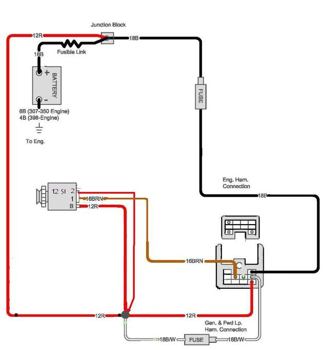
- Circuitry: The diagram shows the electrical connections and current flow.
- Components: It identifies the alternator, battery, voltage regulator, and other related components.
- Connections: The diagram illustrates the wiring and connectors used to establish electrical connections.
- Troubleshooting: It aids in diagnosing electrical faults and identifying potential issues.
- Installation: The diagram provides guidance for proper alternator installation and wiring.
- Maintenance: It assists in regular maintenance and inspection of the charging system.
- Safety: The diagram emphasizes safe working practices and precautions to avoid electrical hazards.
- Compatibility: It ensures the compatibility of the alternator and wiring diagram with specific Ford vehicle models.
These aspects are interconnected, providing a comprehensive understanding of Ford 2g Alternator Wiring Diagrams. By comprehending these aspects, technicians and enthusiasts can effectively maintain and troubleshoot electrical systems, ensuring optimal charging system performance and vehicle reliability.
Circuitry
Understanding the circuitry of a Ford 2g alternator wiring diagram is essential for troubleshooting, repair, and maintenance. The diagram provides a visual representation of the electrical connections and current flow, enabling a comprehensive understanding of the charging system.
- Connections: The diagram shows the wiring and connectors used to establish electrical connections between the alternator, battery, voltage regulator, and other related components.
- Current Flow: The diagram illustrates the path of current flow throughout the charging system, from the alternator to the battery and various electrical components.
- Components: The diagram identifies the specific components involved in the charging system, such as diodes, transistors, and resistors, and their respective roles.
- Testing Points: The diagram may include designated testing points for voltage and continuity checks, aiding in diagnosing electrical faults and verifying proper system operation.
Comprehending the circuitry of a Ford 2g alternator wiring diagram empowers technicians and enthusiasts to effectively maintain and troubleshoot electrical systems, ensuring optimal charging system performance and vehicle reliability. By tracing the electrical connections and current flow, it becomes possible to identify potential issues, perform accurate repairs, and ensure the proper functioning of the charging system.
Components
In a Ford 2g alternator wiring diagram, identifying the alternator, battery, voltage regulator, and other related components is crucial for understanding and servicing the charging system. These components play critical roles in generating, regulating, and distributing electrical power throughout the vehicle.
The alternator is the heart of the charging system, converting mechanical energy from the engine into electrical energy. The battery stores electrical energy, providing power when the engine is off and supplementing the alternator at low engine speeds. The voltage regulator ensures that the alternator maintains the correct output voltage, preventing overcharging or undercharging of the battery and electrical components.
Understanding the relationship between these components is essential for effective troubleshooting and repair. For instance, a faulty alternator can lead to insufficient charging of the battery, resulting in starting issues or electrical system malfunctions. A malfunctioning voltage regulator can cause overcharging, damaging the battery and other electrical components, or undercharging, leading to insufficient power supply.
Real-life examples further illustrate the importance of component identification in Ford 2g alternator wiring diagrams. In a scenario where the battery fails to hold a charge, tracing the wiring diagram helps identify potential issues with the alternator, voltage regulator, or electrical connections. Understanding the role of each component enables technicians to pinpoint the root cause and perform targeted repairs.
In conclusion, the identification of components in Ford 2g alternator wiring diagrams empowers technicians and enthusiasts to comprehensively diagnose, repair, and maintain the charging system. By comprehending the interconnections and functions of these components, it becomes possible to effectively address electrical system issues, ensuring optimal vehicle performance and reliability.
Connections
In the context of a Ford 2g alternator wiring diagram, connections play a crucial role in establishing and maintaining electrical circuits. The diagram illustrates the wiring and connectors used to connect the alternator to the battery, voltage regulator, and other electrical components, forming a network that enables the flow of electrical current.
Without proper connections, the alternator would be unable to generate and distribute electrical power, leading to a non-functional charging system. Loose or corroded connections can cause resistance, voltage drops, and intermittent electrical issues. Understanding the diagram and ensuring secure connections is therefore critical for the proper functioning of the charging system.
Real-life examples highlight the importance of connections in Ford 2g alternator wiring diagrams. A common issue is the failure of the alternator to charge the battery due to loose or broken connections. Identifying and memperbaiki these connections resolves the charging problem and restores proper electrical system operation.
In summary, connections in a Ford 2g alternator wiring diagram are essential for establishing and maintaining electrical circuits, ensuring the proper functioning of the charging system. Understanding the diagram and ensuring proper connections is crucial for troubleshooting, repair, and maintenance, preventing electrical issues and ensuring optimal vehicle performance.
Troubleshooting
In the context of Ford 2g alternator wiring diagrams, troubleshooting is a crucial aspect that enables technicians to identify and resolve electrical faults. By analyzing the diagram and understanding the electrical connections, potential problems can be pinpointed and rectified.
- Fault Identification: The diagram aids in identifying potential issues by providing a visual representation of the charging system. By examining the connections and components, technicians can identify areas where faults may occur, such as loose connections, damaged wires, or faulty components.
- Voltage Checks: The diagram specifies testing points where voltage measurements can be taken. By comparing the measured voltages to the specified values, technicians can assess the performance of the alternator, voltage regulator, and battery, helping to diagnose issues related to voltage regulation or charging.
- Circuit Continuity: The diagram enables continuity checks to ensure proper electrical connections. By using a multimeter, technicians can test for continuity between components and identify breaks or faults in the wiring, which can cause intermittent electrical issues or prevent the charging system from functioning correctly.
- Component Testing: The diagram helps in isolating faulty components by providing information on how to test individual components, such as the alternator, voltage regulator, or diodes. By following the specified testing procedures, technicians can determine if a particular component is malfunctioning and requires replacement.
Troubleshooting using Ford 2g alternator wiring diagrams empowers technicians to systematically diagnose and resolve electrical faults, ensuring optimal charging system performance and preventing vehicle breakdowns. It provides a roadmap for identifying and addressing potential issues, enabling efficient repairs and maintaining the reliability of the electrical system.
Installation
Within the context of “Ford 2g Alternator Wiring Diagram,” the aspect of installation plays a critical role in ensuring the proper functioning and longevity of the charging system. The diagram provides detailed guidance for technicians and enthusiasts to correctly install and wire the alternator, ensuring optimal performance and avoiding potential electrical issues.
- Component Compatibility: The diagram specifies the compatibility of the alternator with the specific Ford vehicle model, ensuring that the alternator’s electrical characteristics and mounting configuration match the vehicle’s requirements.
- Wiring Harness Connections: The diagram illustrates the proper connections between the alternator and the vehicle’s wiring harness, including the battery, voltage regulator, and other electrical components. Correct wiring ensures efficient current flow and prevents short circuits or electrical malfunctions.
- Mounting and Tension: The diagram provides instructions for securely mounting the alternator and adjusting the belt tension. Proper mounting prevents excessive vibration or misalignment, while correct belt tension ensures efficient power transmission from the engine to the alternator.
- Grounding: The diagram specifies the grounding points for the alternator, ensuring a solid electrical connection to the vehicle’s chassis. Proper grounding prevents electrical noise, voltage fluctuations, and potential damage to the alternator or other electrical components.
Understanding and following the installation guidance provided in the “Ford 2g Alternator Wiring Diagram” is essential for successful alternator replacement or installation. By ensuring proper component compatibility, correct wiring connections, secure mounting, and adequate grounding, technicians can guarantee the reliable operation of the charging system and prevent costly electrical problems down the road.
Maintenance
Within the context of “Ford 2g Alternator Wiring Diagram,” maintenance plays a pivotal role in ensuring the longevity and optimal performance of the charging system. The diagram provides valuable guidance for regular maintenance and inspection procedures, enabling technicians and enthusiasts to proactively identify and address potential issues before they lead to costly repairs or breakdowns.
- Battery Inspection: The diagram aids in inspecting the battery terminals for corrosion or loose connections, which can hinder current flow and affect charging efficiency. Regular cleaning and tightening of terminals ensure proper electrical contact and prevent voltage drop issues.
- Belt Inspection and Adjustment: The diagram provides guidance on inspecting and adjusting the alternator belt tension. A loose belt can cause slippage, reducing alternator output and leading to undercharging. Proper belt tension ensures efficient power transmission from the engine to the alternator.
- Alternator Cleaning: The diagram highlights the importance of cleaning the alternator exterior to remove dirt, debris, and corrosion. Accumulated grime can impede heat dissipation and affect alternator performance. Regular cleaning helps maintain optimal operating temperatures and extends alternator life.
- Voltage Regulator Testing: The diagram assists in testing the voltage regulator using specified procedures. A faulty voltage regulator can lead to overcharging or undercharging, damaging the battery and other electrical components. Regular testing helps identify potential issues and prevent costly repairs.
Understanding and following the maintenance guidance provided in the “Ford 2g Alternator Wiring Diagram” empowers individuals to maintain a healthy charging system, ensuring reliable electrical power supply and preventing premature component failure. Regular maintenance not only extends the lifespan of electrical components but also contributes to overall vehicle reliability and safety.
Safety
When working with electrical systems, safety should always be a top priority. Ford 2g Alternator Wiring Diagrams play a crucial role in ensuring the safety of technicians and enthusiasts alike by emphasizing safe working practices and precautions to avoid electrical hazards.
- Proper Insulation: Electrical components in the charging system, such as wires and terminals, should be adequately insulated to prevent accidental contact with live conductors. The diagram highlights the need for proper insulation to safeguard against electrical shocks.
- Grounding: The alternator and other electrical components must be properly grounded to provide a safe path for electrical current to flow. The diagram indicates the appropriate grounding points to avoid potential electrical faults and ensure the safe operation of the charging system.
- Voltage Testing: Before performing any work on the charging system, it is essential to verify that the system is not energized. The diagram provides guidance on safe voltage testing procedures to prevent electrical shocks and damage to sensitive components.
- Protective Gear: When working with electrical systems, it is crucial to wear appropriate protective gear, such as insulated gloves and safety glasses. The diagram reminds technicians of the importance of personal protection to minimize the risk of injury from electrical hazards.
Understanding and adhering to the safety guidelines outlined in the Ford 2g Alternator Wiring Diagram is paramount to ensure a safe working environment. By following these precautions, technicians can minimize the risk of electrical hazards, preventing accidents, injuries, and damage to electrical components. Prioritizing safety not only protects individuals but also ensures the proper functioning of the charging system, contributing to overall vehicle reliability and performance.
Compatibility
Within the context of “Ford 2g Alternator Wiring Diagram,” compatibility plays a vital role in ensuring the proper functioning and performance of the charging system. The diagram is designed to be compatible with specific Ford vehicle models, taking into account various factors that affect the electrical system’s operation.
- Electrical Specifications: The alternator’s electrical specifications, such as voltage output, amperage rating, and voltage regulation, must match the requirements of the specific Ford vehicle model. The wiring diagram provides the necessary information to ensure compatibility and prevent issues like overcharging or undercharging.
- Mounting Configuration: The alternator’s physical configuration, including its mounting points and dimensions, should align with the vehicle’s design. The wiring diagram specifies the mounting requirements to ensure proper fitment and prevent installation problems.
- Connector Compatibility: The electrical connectors on the alternator must match the wiring harness of the specific Ford vehicle model. The wiring diagram identifies the connector types and pin assignments to facilitate seamless electrical connections.
- Control Systems: Some Ford vehicle models may have specific control systems that interface with the alternator, such as voltage sensing or load management systems. The wiring diagram provides information on these control systems and their compatibility with the alternator, ensuring proper communication and functionality.
By considering these compatibility factors, the “Ford 2g Alternator Wiring Diagram” enables technicians and enthusiasts to select the appropriate alternator and correctly install and wire it into the vehicle’s electrical system. This ensures optimal charging performance, prevents electrical malfunctions, and contributes to the overall reliability and performance of the vehicle.


Related Posts


