A “Trailer Lights Wiring Diagram” visually represents the electrical connections between a towing vehicle and a trailer’s light system. It provides a clear roadmap for installing and maintaining lights, ensuring safe communication between both units while on the road.
Wiring diagrams play a crucial role in trailer safety and compliance. They help prevent electrical hazards, such as shorts and fires, by guiding proper wiring procedures. By following the diagram’s instructions, individuals can effectively connect the trailer’s lights to the appropriate power sources on the towing vehicle, ensuring correct function and visibility.
Historically, trailer wiring diagrams were primarily paper-based, requiring meticulous study and careful interpretation. However, the advent of digital and interactive diagrams has significantly simplified the process. These modern diagrams often feature color-coded wires and detailed annotations, making it easier for users to navigate and understand the electrical connections.
A “Trailer Lights Wiring Diagram” serves as a crucial guide for ensuring the proper functionality and safety of a trailer’s lighting system. Understanding the essential aspects of these diagrams is paramount for effective trailer wiring and maintenance.
- Connections: Outlining the electrical pathways between the towing vehicle and the trailer’s lights.
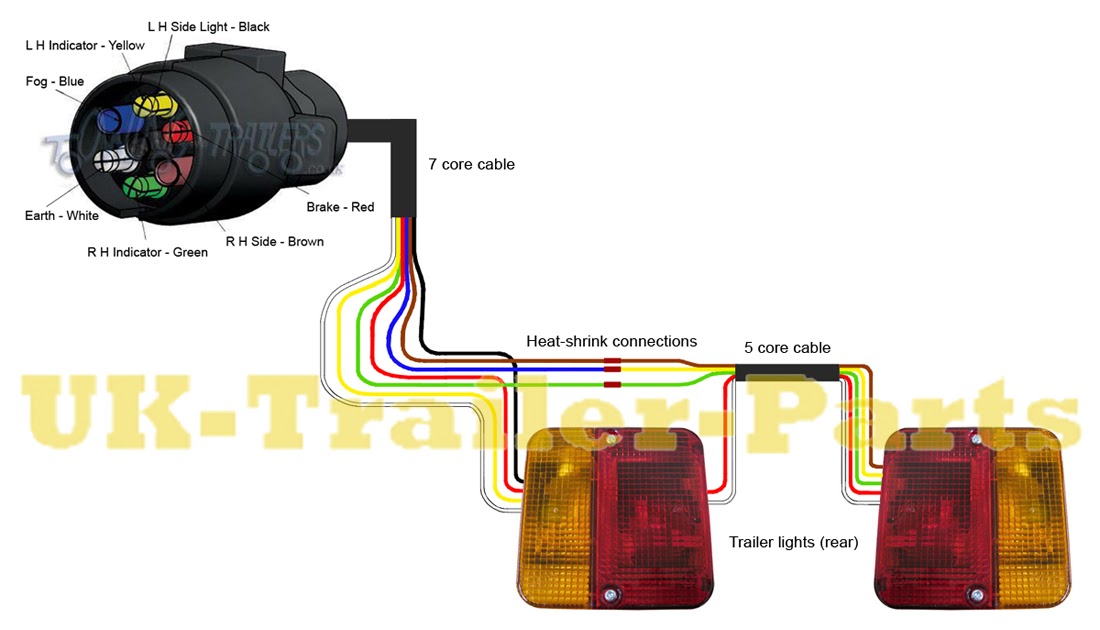
- Color-coding: Utilizing standardized wire colors for easy identification and connection.
- Functionality: Depicting the specific roles of each wire in powering and controlling the lights.
- Safety: Highlighting proper grounding and fusing practices to prevent electrical hazards.
- Compliance: Ensuring adherence to legal requirements and industry standards for lighting systems.
- Troubleshooting: Providing a roadmap for diagnosing and resolving electrical issues.
- Maintenance: Facilitating regular inspections and repairs to maintain optimal lighting performance.
- Customization: Allowing for modifications and additions to the lighting system as needed.
These aspects collectively contribute to the safe and efficient operation of a trailer’s lighting system. Proper wiring not only ensures visibility and communication on the road but also prevents electrical problems that could lead to accidents or equipment damage.
Connections
A “Trailer Lights Wiring Diagram” serves as a blueprint for the electrical connections between a towing vehicle and its trailer, ensuring the proper functioning of the trailer’s lighting system. At the core of this diagram lies the crucial aspect of “Connections: Outlining the electrical pathways between the towing vehicle and the trailer’s lights.” This element provides a detailed roadmap of how electrical power is distributed from the towing vehicle’s electrical system to each individual light on the trailer.
Without a clear understanding of these electrical pathways, haphazard wiring can lead to a multitude of problems. Incorrect connections can result in lights not functioning, malfunctioning erratically, or even posing electrical hazards such as shorts or fires. By carefully following the designated connections outlined in a “Trailer Lights Wiring Diagram,” individuals can ensure that each light is properly grounded and receives the appropriate power, ensuring reliable and safe operation.
Real-life examples of “Connections: Outlining the electrical pathways between the towing vehicle and the trailer’s lights.” within a “Trailer Lights Wiring Diagram” include:
- The connection from the towing vehicle’s battery to the trailer’s ground wire.
- The connection from the towing vehicle’s taillight circuit to the trailer’s taillights.
- The connection from the towing vehicle’s turn signal circuit to the trailer’s turn signals.
- The connection from the towing vehicle’s brake light circuit to the trailer’s brake lights.
Understanding these connections is essential for proper trailer wiring and maintenance. By adhering to the designated connections outlined in a “Trailer Lights Wiring Diagram,” individuals can ensure the safety and functionality of their trailer’s lighting system, promoting visibility and communication on the road.
Color-coding
Within the intricate realm of “Trailer Lights Wiring Diagrams,” color-coding emerges as a cornerstone of clarity and efficiency. Standardized wire colors serve as a universal language, enabling effortless identification and connection during the wiring process.
- Color-coded Wires: Each wire is assigned a specific color, such as brown for ground, yellow for left turn signal, and green for right turn signal, ensuring quick and accurate identification.
- Simplified Troubleshooting: Color-coding aids in troubleshooting electrical issues. By tracing the colored wires, one can swiftly pinpoint the source of a malfunction, saving time and frustration.
- Industry Standards: Adherence to color-coding standards ensures compatibility between different makes and models of towing vehicles and trailers, promoting uniformity and safety.
Color-coding not only simplifies the wiring process but also enhances the safety and reliability of trailer lighting systems. By utilizing standardized wire colors, individuals can confidently establish secure electrical connections, minimizing the risk of errors and maximizing the functionality of their trailer’s lighting system.
Functionality
Within the intricate network of a “Trailer Lights Wiring Diagram,” “Functionality: Depicting the specific roles of each wire in powering and controlling the lights” takes center stage, establishing the electrical pathways that govern the trailer’s lighting system. Each wire, meticulously assigned a color-coded identity, plays a predetermined role in ensuring the proper functioning and safety of the trailer’s lights.
The functionality aspect of a “Trailer Lights Wiring Diagram” lies in its ability to delineate the specific purpose of each wire. By deciphering the color-coded scheme, individuals gain a comprehensive understanding of the electrical architecture, enabling them to confidently connect and control the trailer’s lighting system. This understanding empowers them to troubleshoot electrical issues efficiently, minimizing downtime and maximizing the reliability of their trailer’s lighting system.
In real-life applications, “Functionality: Depicting the specific roles of each wire in powering and controlling the lights” manifests in various scenarios. For instance, the brown wire designated for grounding establishes a crucial connection between the trailer’s electrical system and the chassis, ensuring a safe and stable electrical environment. The yellow wire, responsible for the left turn signal, carries the electrical current that activates the trailer’s left turn signal lights, enabling clear communication of the driver’s intentions on the road.
Harnessing the understanding of “Functionality: Depicting the specific roles of each wire in powering and controlling the lights” empowers individuals to maintain and troubleshoot their trailer’s lighting system effectively. By comprehending the intricate connections and electrical pathways, they can proactively address potential issues, ensuring the safety and functionality of their trailer’s lighting system, contributing to a safer and more informed driving experience.
Safety
In the realm of “Trailer Lights Wiring Diagrams,” “Safety: Highlighting proper grounding and fusing practices to prevent electrical hazards” emerges as a cornerstone of responsible electrical design. This aspect of the diagram serves as a beacon of caution, guiding individuals toward secure and reliable wiring practices that safeguard against electrical hazards.
Grounding, the process of providing a conductive path to the ground, plays a critical role in electrical safety. By establishing a designated pathway for electrical current to flow, grounding prevents uncontrolled electrical flow that could lead to shocks, fires, or equipment damage. Fusing, on the other hand, involves incorporating a sacrificial device that breaks the circuit in the event of an excessive current flow, effectively preventing damage to the electrical system and its components.
Within the context of a “Trailer Lights Wiring Diagram,” “Safety: Highlighting proper grounding and fusing practices to prevent electrical hazards” manifests in various ways. For instance, the diagram may specify the use of a dedicated grounding wire, typically colored green or bare copper, to connect the trailer’s frame to the towing vehicle’s chassis. This grounding wire provides a safe and reliable path for electrical current to flow, minimizing the risk of electrical shock or fire.
Furthermore, the diagram may include instructions on incorporating fuses into the trailer’s lighting circuits. Fuses, typically housed in small plastic holders, are designed to melt and break the circuit in the event of an excessive current flow. By sacrificing themselves, fuses protect the wiring and components from damage caused by electrical overloads or short circuits.
Understanding the importance of “Safety: Highlighting proper grounding and fusing practices to prevent electrical hazards” empowers individuals to make informed decisions when wiring and maintaining their trailer’s lighting system. By adhering to the guidelines outlined in the diagram, they can proactively mitigate electrical hazards, ensuring the safety and reliability of their trailer’s lighting system.
Compliance
Within the realm of “Trailer Lights Wiring Diagrams,” the aspect of “Compliance: Ensuring adherence to legal requirements and industry standards for lighting systems” emerges as a cornerstone of responsible electrical design and safe operation. This element of the diagram serves as a guide towards ensuring that the trailer’s lighting system meets the minimum requirements set forth by regulatory bodies and industry best practices, promoting safety and legal compliance.
-
Legal Requirements:
Trailer lighting systems must adhere to specific legal requirements mandated by various regulatory bodies. These requirements may vary depending on the jurisdiction, but generally include specifications for the number, placement, and visibility of lights, ensuring compliance with local laws and regulations.
-
Industry Standards:
In addition to legal requirements, trailer lighting systems should also conform to industry standards established by organizations such as the Society of Automotive Engineers (SAE) and the National Electrical Manufacturers Association (NEMA). These standards provide guidelines for the design, installation, and maintenance of trailer lighting systems, promoting uniformity, safety, and interchangeability.
-
Safety Implications:
Compliance with legal requirements and industry standards is not merely a matter of avoiding penalties or fines; it is a fundamental aspect of ensuring the safety of the trailer and its occupants. Properly functioning lighting systems are crucial for enhancing visibility, communicating intentions to other road users, and preventing accidents.
-
DOT Approval:
In many jurisdictions, trailer lighting systems must bear the Department of Transportation (DOT) mark of approval. This mark signifies that the lighting system meets the minimum safety requirements by the federal government, providing assurance of compliance and quality.
By adhering to the guidelines and specifications outlined in the “Compliance: Ensuring adherence to legal requirements and industry standards for lighting systems” aspect of a “Trailer Lights Wiring Diagram,” individuals can confidently establish and maintain safe and compliant trailer lighting systems. This not only ensures legal compliance but also contributes to the overall safety and reliability of the trailer’s lighting system, promoting a more secure and informed driving experience.
Troubleshooting
Within the realm of “Trailer Lights Wiring Diagrams,” the aspect of “Troubleshooting: Providing a roadmap for diagnosing and resolving electrical issues” emerges as an indispensable tool for ensuring the reliable and safe functioning of a trailer’s lighting system. This element of the diagram serves as a guide towards identifying, diagnosing, and resolving electrical problems that may arise, empowering individuals to maintain a well-functioning lighting system and address issues promptly.
The connection between “Troubleshooting: Providing a roadmap for diagnosing and resolving electrical issues” and “Trailer Lights Wiring Diagram” is akin to that of a blueprint and a construction project. Just as a blueprint provides a detailed plan for constructing a building, a “Trailer Lights Wiring Diagram” outlines the electrical layout of the trailer’s lighting system. However, unforeseen circumstances or wear and tear over time can lead to electrical issues, and this is where the “Troubleshooting” aspect of the diagram comes into play.
Real-life examples of “Troubleshooting: Providing a roadmap for diagnosing and resolving electrical issues” within “Trailer Lights Wiring Diagram” abound. For instance, the diagram may provide step-by-step instructions on how to trace a circuit to identify a faulty wire or component. It may also include troubleshooting charts that list common electrical problems and their potential causes, guiding individuals towards effective solutions.
The practical applications of understanding “Troubleshooting: Providing a roadmap for diagnosing and resolving electrical issues” are far-reaching. By being able to identify and resolve electrical problems, individuals can minimize downtime, ensure the safety of their trailer’s lighting system, and avoid costly repairs. Moreover, a well-maintained lighting system contributes to the overall safety of the trailer, enhancing visibility and promoting safe driving conditions.
In summary, “Troubleshooting: Providing a roadmap for diagnosing and resolving electrical issues” is a critical component of “Trailer Lights Wiring Diagram,” providing a valuable tool for maintaining and repairing a trailer’s lighting system. By understanding the troubleshooting aspect of the diagram, individuals are empowered to address electrical problems effectively, ensuring the safety and reliability of their trailer’s lighting system.
Maintenance
Within the realm of “Trailer Lights Wiring Diagrams,” the aspect of “Maintenance: Facilitating regular inspections and repairs to maintain optimal lighting performance” emerges as a cornerstone of responsible trailer ownership and safe operation. This element of the diagram serves as a roadmap for proactive maintenance and timely repairs, ensuring that the trailer’s lighting system remains in peak condition, maximizing visibility and minimizing the risk of electrical problems.
The connection between “Maintenance: Facilitating regular inspections and repairs to maintain optimal lighting performance” and “Trailer Lights Wiring Diagram” is akin to that of a periodic checkup and a medical diagnosis. Just as regular checkups help identify and address potential health issues early on, regular maintenance of a trailer’s lighting system can prevent minor problems from escalating into major ones.
Real-life examples of “Maintenance: Facilitating regular inspections and repairs to maintain optimal lighting performance” within “Trailer Lights Wiring Diagram” abound. The diagram may include instructions on how to inspect the trailer’s lighting system for loose connections, damaged wires, or faulty components. It may also provide guidelines on how to clean and maintain the lighting fixtures, ensuring optimal light output and longevity.
The practical applications of understanding “Maintenance: Facilitating regular inspections and repairs to maintain optimal lighting performance” are far-reaching. By adhering to the maintenance schedule outlined in the “Trailer Lights Wiring Diagram,” individuals can proactively address potential issues, preventing unexpected breakdowns and ensuring the safety and reliability of their trailer’s lighting system. Moreover, regular maintenance can extend the lifespan of the lighting components, reducing the need for costly replacements.
In summary, “Maintenance: Facilitating regular inspections and repairs to maintain optimal lighting performance” is a critical component of “Trailer Lights Wiring Diagram,” providing valuable guidance for the upkeep and longevity of a trailer’s lighting system. By understanding and implementing the maintenance recommendations outlined in the diagram, individuals can ensure that their trailer’s lighting system remains in peak condition, promoting safe and reliable operation.
Customization
Within the realm of “Trailer Lights Wiring Diagrams,” the aspect of “Customization: Allowing for modifications and additions to the lighting system as needed” emerges as a cornerstone of versatility and personalization. This element of the diagram provides a framework for adapting the trailer’s lighting system to specific requirements or preferences, enabling individuals to tailor the lighting setup to their unique needs and applications.
The connection between “Customization: Allowing for modifications and additions to the lighting system as needed” and “Trailer Lights Wiring Diagram” is akin to that of an artist’s palette and a blank canvas. Just as an artist uses a palette to mix and match colors to create their desired artwork, a “Trailer Lights Wiring Diagram” provides the foundation upon which individuals can customize their lighting system to suit their specific requirements.
Real-life examples of “Customization: Allowing for modifications and additions to the lighting system as needed” within “Trailer Lights Wiring Diagram” abound. The diagram may include instructions on how to add additional lighting fixtures, such as auxiliary brake lights or side marker lights, to enhance visibility and safety. It may also provide guidance on how to modify the wiring to accommodate different types of lighting fixtures or control systems, enabling individuals to integrate cutting-edge lighting technologies into their trailer’s lighting system.
The practical applications of understanding “Customization: Allowing for modifications and additions to the lighting system as needed” are far-reaching. By harnessing the customization capabilities outlined in the “Trailer Lights Wiring Diagram,” individuals can tailor their trailer’s lighting system to meet specific requirements or preferences. Whether it’s for enhanced visibility, improved safety, or simply a personalized aesthetic, the ability to customize the lighting system empowers individuals to create a lighting setup that meets their unique needs and preferences.
In summary, “Customization: Allowing for modifications and additions to the lighting system as needed” is a critical component of “Trailer Lights Wiring Diagram,” providing a framework for versatility and personalization. By understanding and implementing the customization options outlined in the diagram, individuals can adapt their trailer’s lighting system to suit their specific requirements, enhancing visibility, safety, and aesthetics.


Related Posts


