A “3 Phase Air Compressor Wiring Diagram” is a visual representation of the electrical connections required to operate a 3-phase air compressor. It shows the proper connections between the motor, capacitor, pressure switch, and other electrical components. For instance, a wiring diagram for a 5 horsepower 3-phase air compressor might include connections for a 230-volt power supply, a motor with three terminals, a capacitor with two terminals, and a pressure switch with two terminals.
Wiring diagrams are essential for ensuring the safe and efficient operation of an air compressor. By following the instructions provided in the diagram, electricians can connect the electrical components correctly, ensuring that the compressor will start, run, and stop properly. Additionally, wiring diagrams can be helpful for troubleshooting problems with an air compressor. By examining the diagram, electricians can identify potential electrical faults and take the necessary steps to repair them.
One key historical development in the field of air compressor wiring is the introduction of the National Electrical Code (NEC). The NEC is a set of safety standards that govern the installation and maintenance of electrical equipment in the United States. The NEC includes specific requirements for the wiring of air compressors, including the use of proper wire sizes, conduit, and connectors. The NEC has helped to ensure the safety of air compressors in the workplace and has saved lives.
This article will provide a more in-depth look at the wiring of 3-phase air compressors, including the different types of wiring diagrams, the components of an air compressor wiring system, and the NEC requirements for air compressor wiring.
3-phase air compressor wiring diagrams are essential for ensuring the safe and efficient operation of air compressors. They provide electricians with the information they need to connect the electrical components of an air compressor correctly, ensuring that the compressor will start, run, and stop properly. Wiring diagrams can also be helpful for troubleshooting problems with an air compressor.
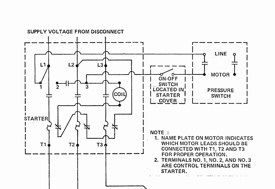
- Components: Wiring diagrams show the different electrical components of an air compressor, including the motor, capacitor, pressure switch, and overload relay.
- Connections: Wiring diagrams show how the electrical components of an air compressor are connected to each other.
- Wire sizes: Wiring diagrams specify the size of wire that should be used for each connection.
- Conduit: Wiring diagrams specify the type of conduit that should be used to protect the wires.
- NEC requirements: Wiring diagrams must comply with the National Electrical Code (NEC), which is a set of safety standards that govern the installation and maintenance of electrical equipment in the United States.
- Troubleshooting: Wiring diagrams can be used to troubleshoot problems with an air compressor.
- Safety: Wiring diagrams help to ensure the safe operation of air compressors.
- Efficiency: Wiring diagrams help to ensure the efficient operation of air compressors.
These are just a few of the key aspects of 3-phase air compressor wiring diagrams. By understanding these aspects, electricians can ensure that air compressors are wired safely and efficiently.
Components
Wiring diagrams for 3-phase air compressors show the different electrical components of the compressor, including the motor, capacitor, pressure switch, and overload relay. These components are essential for the safe and efficient operation of the compressor.
- Motor: The motor is the heart of the air compressor. It converts electrical energy into mechanical energy, which is used to drive the compressor’s pump. Motors for 3-phase air compressors are typically rated for 230 volts or 460 volts.
- Capacitor: The capacitor is used to improve the starting torque of the motor. It stores electrical energy and releases it during the starting cycle of the motor. Capacitors for 3-phase air compressors are typically rated for 2 microfarads or 4 microfarads.
- Pressure switch: The pressure switch is used to control the operation of the compressor. It turns the compressor on when the air pressure in the tank drops below a certain level and turns it off when the air pressure reaches a certain level. Pressure switches for 3-phase air compressors are typically rated for 120 volts or 240 volts.
- Overload relay: The overload relay is used to protect the motor from damage caused by overloads. It trips and turns off the motor if the motor draws too much current. Overload relays for 3-phase air compressors are typically rated for 10 amps or 15 amps.
These are just a few of the key electrical components of a 3-phase air compressor. By understanding the function of these components, electricians can ensure that air compressors are wired safely and efficiently.
Connections
Without proper connections, the electrical components of an air compressor would not be able to function together to power the compressor and generate compressed air. The wiring diagram provides a clear and concise visual representation of how each component is connected to the others, ensuring that the compressor is wired correctly and safely.
A real-life example of the importance of connections in a 3-phase air compressor wiring diagram is the connection between the motor and the capacitor. The capacitor is used to improve the starting torque of the motor, which is essential for getting the compressor up and running. If the capacitor is not properly connected, the motor may not be able to start, or it may start but not run properly.
Understanding the connections between the electrical components of an air compressor is also essential for troubleshooting problems. If the compressor is not working properly, an electrician can use the wiring diagram to identify potential problems and take steps to correct them.
In conclusion, the connections between the electrical components of an air compressor are critical for the safe and efficient operation of the compressor. Wiring diagrams provide a valuable tool for ensuring that the compressor is wired correctly and for troubleshooting problems.
Wire sizes
In a 3-phase air compressor wiring diagram, the size of the wire that is used for each connection is critical for the safe and efficient operation of the compressor. The wire size must be large enough to carry the current that will be flowing through it without overheating. If the wire is too small, it will overheat and could cause a fire.
The current that flows through a wire is determined by the voltage of the circuit and the resistance of the wire. The voltage of a 3-phase air compressor is typically 230 volts or 460 volts. The resistance of a wire is determined by its length, its cross-sectional area, and the material that it is made of.
Wiring diagrams for 3-phase air compressors typically specify the wire size that should be used for each connection. This information is based on the voltage of the circuit, the current that will be flowing through the wire, and the length of the wire.
Real-life examples of the importance of wire size in a 3-phase air compressor wiring diagram include:
- If the wire that is used to connect the motor to the power supply is too small, it could overheat and cause a fire.
- If the wire that is used to connect the pressure switch to the motor is too small, it could cause the motor to overheat and fail.
- If the wire that is used to connect the overload relay to the motor is too small, it could cause the overload relay to trip and shut off the motor.
Understanding the importance of wire size in a 3-phase air compressor wiring diagram is essential for ensuring the safe and efficient operation of the compressor. By following the wire size specifications in the wiring diagram, electricians can help to prevent fires, motor failures, and other problems.
Conduit
In a 3-phase air compressor wiring diagram, the type of conduit that is used to protect the wires is critical for the safe and efficient operation of the compressor. Conduit is a protective casing that is used to enclose and protect the wires from damage. It can be made of metal or plastic, and it comes in a variety of sizes and shapes.
The main purpose of conduit is to protect the wires from physical damage. Wires can be damaged by abrasion, crushing, or cutting. Conduit can also help to protect the wires from moisture, dust, and other environmental hazards.
Wiring diagrams for 3-phase air compressors typically specify the type of conduit that should be used for each connection. This information is based on the voltage of the circuit, the current that will be flowing through the wire, and the environment in which the compressor will be used.
Real-life examples of the importance of conduit in a 3-phase air compressor wiring diagram include:
- If the wires that are used to connect the motor to the power supply are not protected by conduit, they could be damaged by abrasion or crushing. This could cause a fire or an electrical shock.
- If the wires that are used to connect the pressure switch to the motor are not protected by conduit, they could be damaged by moisture or dust. This could cause the pressure switch to malfunction and the compressor to stop working.
- If the wires that are used to connect the overload relay to the motor are not protected by conduit, they could be damaged by heat. This could cause the overload relay to trip and shut off the motor.
Understanding the importance of conduit in a 3-phase air compressor wiring diagram is essential for ensuring the safe and efficient operation of the compressor. By following the conduit specifications in the wiring diagram, electricians can help to prevent fires, electrical shocks, and other problems.
NEC requirements
The NEC is a critical component of 3-phase air compressor wiring diagrams. The NEC provides minimum safety requirements for the installation and maintenance of electrical equipment, including air compressors. These requirements are intended to protect people and property from electrical hazards.
By following the NEC, electricians can help to ensure that 3-phase air compressors are installed and maintained safely. This can help to prevent fires, electrical shocks, and other accidents.
Real-life examples of NEC requirements in 3-phase air compressor wiring diagrams include:
- The NEC requires that the wires used in a 3-phase air compressor wiring diagram be properly sized for the current that will be flowing through them. This helps to prevent overheating and fires.
- The NEC requires that the conduit used to protect the wires in a 3-phase air compressor wiring diagram be properly installed and maintained. This helps to protect the wires from damage and prevents electrical shocks.
- The NEC requires that the electrical components in a 3-phase air compressor wiring diagram be properly connected. This helps to ensure that the compressor operates safely and efficiently.
By understanding the NEC requirements for 3-phase air compressor wiring diagrams, electricians can help to ensure that these compressors are installed and maintained safely. This can help to prevent accidents and protect people and property.
Troubleshooting
Wiring diagrams are essential for troubleshooting problems with 3-phase air compressors. They provide a visual representation of the electrical connections in the compressor, making it easier to identify potential problems. By following the wiring diagram, electricians can trace the electrical circuits and identify any loose connections, damaged wires, or faulty components.
Real-life examples of how wiring diagrams can be used to troubleshoot problems with 3-phase air compressors include:
- If the air compressor is not starting, the wiring diagram can be used to check the connections to the motor and the capacitor.
- If the air compressor is not producing enough air pressure, the wiring diagram can be used to check the connections to the pressure switch and the unloader valve.
- If the air compressor is overheating, the wiring diagram can be used to check the connections to the overload relay and the cooling fan.
Understanding how to use a wiring diagram to troubleshoot problems with a 3-phase air compressor is an essential skill for electricians. By following the wiring diagram, electricians can quickly and easily identify and fix problems, ensuring that the compressor is operating safely and efficiently.
Safety
Wiring diagrams are essential for ensuring the safe operation of air compressors, as they provide a visual representation of the electrical connections in the compressor. This makes it easier to identify potential problems and take steps to correct them before they can cause an accident. For example, a wiring diagram can be used to check the connections to the motor, capacitor, pressure switch, and overload relay. If any of these connections are loose or damaged, it could pose a safety hazard. By following the wiring diagram, electricians can ensure that all of the connections are tight and secure.
Another important safety feature of wiring diagrams is that they help to prevent electrical fires. Electrical fires can be caused by a number of factors, including loose connections, damaged wires, and overloaded circuits. Wiring diagrams can help to prevent these problems by providing a clear and concise guide for installing and maintaining the electrical system of an air compressor. By following the wiring diagram, electricians can ensure that the electrical system is installed correctly and that all of the components are properly sized and protected.
In addition to preventing electrical fires, wiring diagrams can also help to prevent other types of accidents, such as electrical shocks. Electrical shocks can be caused by contact with live wires or terminals. Wiring diagrams can help to prevent electrical shocks by providing a clear and concise guide for installing and maintaining the electrical system of an air compressor. By following the wiring diagram, electricians can ensure that all of the live wires and terminals are properly insulated and protected.
Wiring diagrams are an essential tool for ensuring the safe operation of air compressors. By following the wiring diagram, electricians can help to prevent electrical fires, electrical shocks, and other accidents.
Efficiency
Wiring diagrams are essential for ensuring the efficient operation of air compressors. They provide a visual representation of the electrical connections in the compressor, making it easier to identify and correct potential problems. By following the wiring diagram, electricians can ensure that the compressor is operating at its peak efficiency.
One of the most important ways that wiring diagrams help to improve efficiency is by preventing electrical losses. Electrical losses can occur when there are loose connections, damaged wires, or overloaded circuits. These problems can cause the compressor to work harder than it needs to, which can waste energy and shorten the lifespan of the compressor. Wiring diagrams help to prevent these problems by providing a clear and concise guide for installing and maintaining the electrical system of an air compressor.
Another way that wiring diagrams help to improve efficiency is by ensuring that the compressor is properly sized for the application. An oversized compressor will use more energy than necessary, while an undersized compressor will not be able to meet the demands of the application. Wiring diagrams help to prevent these problems by providing information on the electrical requirements of the compressor. This information can be used to select the correct size compressor for the application.
Understanding the connection between wiring diagrams and the efficient operation of air compressors is essential for electricians and anyone who uses air compressors. By following the wiring diagram, electricians can ensure that the compressor is installed correctly, that all of the components are properly sized and protected, and that the compressor is operating at its peak efficiency.


Related Posts


