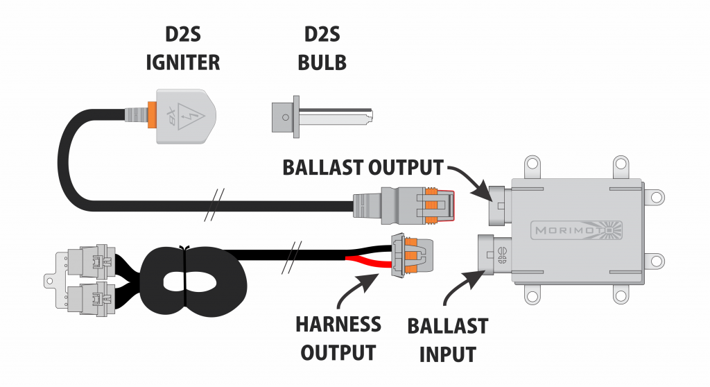
A HID ballast wiring diagram illustrates the electrical connections required to install a High-Intensity Discharge (HID) lighting system. It provides a visual guide for connecting the ballast, bulbs, igniter, and power source, ensuring proper operation and safety.
The diagram outlines the sequence of electrical connections, wire types, and grounding requirements. It ensures that the correct voltage and current are supplied to each component, allowing for optimal performance and longevity of the HID system. By following the wiring diagram, technicians can avoid incorrect connections that could lead to damage or electrical hazards.
HID ballast wiring diagrams are introduced in the installation of automotive lighting systems, industrial lighting, and commercial signage to enhance visibility and energy efficiency. They serve as a critical tool for ensuring the safe and effective operation of HID lighting systems, helping maintain optimal illumination and extend equipment lifespan.
HID ballast wiring diagrams are essential for understanding how to connect and install High-Intensity Discharge (HID) lighting systems safely and effectively. They provide a comprehensive overview of the electrical connections required, ensuring optimal performance and longevity of the HID system.
- Accuracy: Wiring diagrams guarantee that all electrical connections are made correctly, preventing potential hazards or damage to the HID system.
- Safety: By adhering to the wiring diagram, technicians can ensure that the HID system operates safely, minimizing the risk of electrical fires or malfunctions.
- Performance: Proper wiring ensures that the ballast provides the correct voltage and current to the HID bulbs, resulting in optimal light output and longevity.
- Compatibility: Wiring diagrams account for the specific electrical requirements of different HID components, ensuring compatibility between the ballast, bulbs, and igniter.
- Troubleshooting: In case of any issues with the HID system, the wiring diagram serves as a valuable troubleshooting tool, helping identify potential problems.
- Customization: Wiring diagrams can be adapted to accommodate specific installation requirements, such as custom lighting configurations or integration with existing electrical systems.
- Industry Standards: Wiring diagrams adhere to established industry standards, ensuring compliance with electrical codes and safety regulations.
- Simplicity: Despite their technical nature, wiring diagrams are typically presented in a clear and concise manner, making them easy to understand and follow.
Overall, HID ballast wiring diagrams are indispensable for the proper installation, operation, and maintenance of HID lighting systems. They provide a detailed roadmap for electrical connections, promoting safety, performance, and longevity, while adhering to industry standards and simplifying the installation process.
Accuracy
Accuracy is paramount in HID ballast wiring diagrams to ensure safe and reliable operation of the HID lighting system. Incorrect connections can lead to electrical hazards, damage to the HID components, or even personal injury. By providing a precise guide for connecting the ballast, bulbs, igniter, and power source, the wiring diagram helps prevent these risks.
For instance, improper wiring of the ballast can result in a short circuit, potentially causing a fire. Similarly, incorrect connections of the HID bulbs can lead to premature failure or flickering, compromising the lighting performance. The wiring diagram ensures that each component is connected to the correct terminals with the proper polarity, eliminating these hazards.
In practical applications, HID ballast wiring diagrams are essential for technicians and installers. They streamline the installation process, reducing the risk of errors and ensuring the system operates as intended. Furthermore, these diagrams serve as valuable troubleshooting tools, helping identify and rectify any issues that may arise.
In summary, the accuracy of HID ballast wiring diagrams is critical for ensuring the safety, performance, and longevity of HID lighting systems. They provide a comprehensive roadmap for electrical connections, preventing hazards and guaranteeing optimal operation.
Safety
In the context of HID ballast wiring diagrams, safety is paramount. By meticulously following the wiring diagram, technicians can guarantee that the HID system operates safely, minimizing the risk of electrical fires or malfunctions. This is achieved through precise instructions for connecting the ballast, bulbs, igniter, and power source, ensuring proper electrical connections and preventing hazards.
For example, incorrect wiring of the ballast can lead to a short circuit, potentially causing a fire. The wiring diagram eliminates this risk by providing a clear roadmap for connecting the ballast to the power source and HID bulbs. Similarly, improper connections of the HID bulbs can result in premature failure or flickering, compromising the lighting performance. The wiring diagram ensures that the bulbs are connected to the correct terminals with the proper polarity, preventing these issues.
In practical applications, HID ballast wiring diagrams are essential for ensuring the safety of HID lighting systems. They serve as a valuable tool for technicians and installers, guiding them through the installation process and minimizing the risk of errors. By adhering to the wiring diagram, technicians can prevent electrical hazards, ensure the system operates as intended, and provide safe and reliable illumination.
In summary, the safety aspect of HID ballast wiring diagrams is crucial for preventing electrical fires and malfunctions. By providing accurate and comprehensive instructions for electrical connections, these diagrams empower technicians to install and maintain HID lighting systems safely and effectively, ensuring the well-being of users and the integrity of the lighting system.
Performance
In the context of HID ballast wiring diagrams, performance is a critical aspect directly influenced by the proper wiring of the system. The wiring diagram provides a detailed blueprint for connecting the ballast, bulbs, igniter, and power source, ensuring that the ballast delivers the correct voltage and current to the HID bulbs.
Optimal light output is achieved when the ballast provides the HID bulbs with the correct voltage and current. This ensures that the bulbs operate at their intended brightness and color temperature, providing the desired illumination. Improper wiring can lead to insufficient or excessive voltage and current, resulting in reduced light output, premature bulb failure, or damage to the ballast.
Longevity is another crucial factor affected by proper wiring. When the ballast provides the correct voltage and current, the HID bulbs experience less stress and strain, leading to a longer lifespan. This reduces the frequency of bulb replacements and maintenance costs, ensuring sustained high-quality illumination.
Real-life examples of the importance of proper wiring in HID ballast wiring diagrams are evident in various applications. In automotive lighting, correctly wired HID systems provide superior visibility and road illumination, enhancing driving safety. In commercial lighting, proper wiring ensures that HID lamps operate efficiently, reducing energy consumption and maintenance costs. Additionally, in industrial settings, properly wired HID systems provide optimal lighting for tasks requiring high visibility and precision.
The practical significance of understanding the connection between performance and proper wiring in HID ballast wiring diagrams lies in ensuring optimal lighting performance and longevity. By adhering to the wiring diagram and connecting the components correctly, technicians and installers can maximize light output, extend bulb life, and minimize system downtime.
Compatibility
In the context of HID ballast wiring diagrams, compatibility is critical for ensuring that the ballast, bulbs, and igniter work together seamlessly to produce optimal lighting performance. The wiring diagram serves as a roadmap, outlining the specific electrical connections required for each component, taking into account their unique electrical characteristics.
For instance, different HID bulbs have varying voltage and current requirements. The wiring diagram specifies the correct ballast for each bulb type, ensuring that the ballast provides the appropriate electrical output to power the bulb efficiently. Similarly, the igniter requires a specific voltage and pulse duration to trigger the bulb’s ignition. The wiring diagram provides the necessary details to connect the igniter correctly, ensuring reliable and consistent bulb ignition.
Real-life examples of the importance of compatibility in HID ballast wiring diagrams can be found in various applications. In automotive lighting systems, HID bulbs are used for their high intensity and energy efficiency. The wiring diagram ensures that the ballast and igniter are compatible with the vehicle’s electrical system, providing optimal lighting performance without compromising electrical stability.
In summary, compatibility is a cornerstone of HID ballast wiring diagrams. By accounting for the specific electrical requirements of different HID components, the wiring diagram ensures seamless integration, optimal performance, and long-term reliability of the HID lighting system.
Troubleshooting
In the context of HID ballast wiring diagrams, troubleshooting plays a crucial role in maintaining the optimal performance and longevity of the HID lighting system. The wiring diagram provides a comprehensive overview of the electrical connections, enabling technicians to identify and address potential issues effectively.
- Electrical Continuity: The wiring diagram helps verify the electrical continuity of the HID system. By testing the continuity of wires, connections, and components, technicians can identify any breaks, loose connections, or faulty components that may disrupt the proper functioning of the system.
- Voltage and Current Measurements: The wiring diagram guides technicians in measuring voltage and current at various points in the circuit. Comparing these measurements with the specified values allows them to identify potential issues such as incorrect ballast output, insufficient power supply, or excessive current draw.
- Bulb Diagnostics: The wiring diagram provides insights into the electrical requirements of the HID bulbs. By analyzing the bulb’s voltage, current, and ignition characteristics, technicians can determine if the bulb is functioning correctly or needs replacement.
- Igniter Troubleshooting: The wiring diagram assists in troubleshooting the HID igniter, a critical component responsible for triggering the bulb’s ignition. Technicians can check the igniter’s voltage and pulse duration to ensure it is operating within specifications.
The ability to troubleshoot HID lighting systems using the wiring diagram empowers technicians to diagnose and resolve issues efficiently, ensuring the continued reliability and performance of the lighting system.
Customization
In the realm of HID ballast wiring diagrams, customization plays a significant role in tailoring lighting systems to meet specific requirements. Wiring diagrams provide a flexible framework that can be adapted to accommodate various installation scenarios, enabling the integration of HID lighting into custom lighting configurations and existing electrical systems.
- Custom Lighting Configurations:HID ballast wiring diagrams allow for the customization of lighting configurations to suit unique architectural or aesthetic needs. By modifying the wiring diagram, installers can create bespoke lighting arrangements, such as multi-bulb setups, geometric patterns, or integration with architectural features.
- Integration with Existing Electrical Systems:Wiring diagrams facilitate the seamless integration of HID lighting into existing electrical systems. By adapting the diagram to match the electrical characteristics of the existing system, installers can ensure compatibility and avoid potential conflicts or safety hazards.
- Retrofitting Older Systems:HID ballast wiring diagrams enable the retrofitting of HID lighting into older vehicles or structures. By modifying the diagram to accommodate the unique electrical requirements of the older system, installers can upgrade the lighting system without extensive rewiring or modifications.
- Energy Efficiency Optimization:Customization of wiring diagrams allows for the optimization of energy efficiency. By tailoring the diagram to specific usage patterns and environmental conditions, installers can minimize energy consumption and maximize the efficiency of the HID lighting system.
Customization in HID ballast wiring diagrams empowers lighting designers and installers with the flexibility to adapt lighting systems to diverse requirements. It enables the creation of unique lighting configurations, seamless integration into existing infrastructure, and the optimization of energy efficiency, ultimately enhancing the functionality, aesthetics, and sustainability of HID lighting systems.
Industry Standards
In the context of HID ballast wiring diagrams, industry standards play a pivotal role in ensuring the safety, reliability, and compliance of HID lighting systems. Wiring diagrams that adhere to established industry standards provide a solid foundation for proper installation, operation, and maintenance of HID lighting systems.
- Electrical Code Compliance: Wiring diagrams align with the requirements of national and local electrical codes, ensuring that HID lighting systems meet the minimum safety standards. This compliance minimizes the risk of electrical fires, shocks, or other hazards.
- Safety Regulations Adherence: Industry standards incorporate safety regulations related to the installation and operation of HID lighting systems. By following these standards, wiring diagrams promote the safe use of HID lighting, reducing the potential for accidents or injuries.
- Component Compatibility: Industry standards help ensure compatibility between different components of the HID lighting system, such as the ballast, bulbs, igniter, and power source. This compatibility reduces the risk of malfunctions or damage caused by mismatched components.
- Quality Assurance: Wiring diagrams that adhere to industry standards undergo rigorous testing and evaluation to ensure their accuracy and effectiveness. This quality assurance process minimizes the likelihood of errors or omissions in the diagrams, enhancing the reliability of HID lighting systems.
In summary, industry standards provide a framework for safe and compliant HID ballast wiring diagrams. By adhering to these standards, lighting designers and installers can ensure that HID lighting systems operate reliably, efficiently, and in accordance with all applicable electrical codes and safety regulations.
Simplicity
In the context of HID ballast wiring diagrams, simplicity is a critical component that enhances their utility and effectiveness. By presenting complex electrical connections in a clear and concise manner, wiring diagrams make it easier for technicians and installers to understand and follow the instructions, leading to safer and more efficient HID lighting system installations.
The simplicity of HID ballast wiring diagrams stems from the use of standardized symbols, color-coding, and logical arrangement of components. These elements provide a visual representation of the electrical connections, reducing the need for extensive text-based instructions. This visual approach makes it easier for individuals with varying levels of electrical knowledge to comprehend the diagrams and perform the necessary installations.
Real-life examples of the importance of simplicity in HID ballast wiring diagrams can be found in various industries. In the automotive sector, simplified wiring diagrams enable technicians to quickly and accurately install HID lighting systems in vehicles, ensuring optimal lighting performance and safety. Similarly, in commercial and industrial settings, clear wiring diagrams guide electricians in integrating HID lighting into complex electrical systems, maximizing energy efficiency and minimizing downtime.
The practical significance of understanding the connection between simplicity and HID ballast wiring diagrams lies in the ability to ensure proper installation, maintenance, and troubleshooting of HID lighting systems. Simplified diagrams empower technicians to confidently handle electrical connections, reducing the risk of errors, electrical hazards, and system malfunctions.
In summary, the simplicity of HID ballast wiring diagrams is a key factor contributing to their effectiveness. By presenting complex electrical connections in a clear and concise manner, wiring diagrams facilitate accurate installations, promote safety, and enable efficient maintenance and troubleshooting of HID lighting systems.


Related Posts


