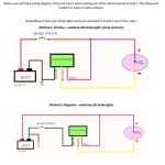
A 480 Volt 3 Phase 12 Lead Motor Wiring Diagram is a detailed plan that illustrates how to connect a 480-volt, three-phase electric motor with 12 leads to a power source. It provides a visual representation of the electrical connections, including the proper placement of wires, terminals, and switches.
This diagram is crucial for ensuring the safe and efficient operation of electric motors. It helps electricians and technicians understand the electrical connections and troubleshoot any issues that may arise. The diagram also allows for proper maintenance and repair of motors, extending their lifespan and reducing downtime.
Historically, the development of standardized wiring diagrams has greatly improved the safety and efficiency of electrical systems. It has enabled the widespread adoption of electric motors in various industries, revolutionizing manufacturing, transportation, and other sectors.
This article will delve deeper into the components, connections, and considerations involved in wiring a 480 Volt 3 Phase 12 Lead Motor, providing comprehensive guidance for electrical professionals.
Understanding the essential aspects of a 480 Volt 3 Phase 12 Lead Motor Wiring Diagram is crucial for ensuring the safe and efficient operation of electric motors. These aspects encompass various dimensions, ranging from electrical connections to maintenance considerations.
- Voltage: 480 volts
- Phases: 3 phases
- Leads: 12 leads
- Wiring: Electrical connections
- Terminals: Connection points
- Switches: Control devices
- Maintenance: Inspection and upkeep
- Troubleshooting: Diagnosing and resolving issues
- Safety: Electrical hazards
- Efficiency: Optimal performance
These aspects are interconnected and play vital roles in the proper functioning of electric motors. For instance, the voltage, phases, and leads determine the electrical characteristics of the motor, while the wiring, terminals, and switches enable the flow of electricity and control the motor’s operation. Proper maintenance and troubleshooting ensure the motor’s longevity and reliability, while safety measures protect against electrical hazards. Understanding and considering these aspects holistically is essential for the effective use and management of electric motors.
Voltage
In the context of a “480 Volt 3 Phase 12 Lead Motor Wiring Diagram,” the voltage aspect refers to the electrical potential of 480 volts that powers the motor. This voltage level is crucial for understanding the motor’s electrical characteristics and ensuring its proper operation.
- Electrical Potential: 480 volts represents the difference in electrical potential between the motor’s terminals, driving the flow of current and generating the magnetic fields necessary for motor operation.
- Power Supply: The wiring diagram specifies the connection to a 480-volt power source, which can be single-phase or three-phase depending on the motor’s design.
- Motor Design: The motor’s internal components, such as windings and insulation, are designed to withstand the 480-volt potential and operate efficiently at this voltage level.
- Safety Considerations: Working with 480 volts requires adherence to strict safety protocols to prevent electrical hazards, including proper grounding, insulation, and protective gear.
Understanding and adhering to the voltage specifications outlined in the wiring diagram are essential for the safe and effective operation of 480-volt motors. Proper installation and maintenance practices, including regular inspections and testing, ensure that the motor operates within its intended voltage range, preventing damage and ensuring optimal performance.
Phases
In the context of “480 Volt 3 Phase 12 Lead Motor Wiring Diagram,” the aspect of “Phases: 3 phases” holds significant importance as it pertains to the electrical characteristics and operation of the motor. A three-phase motor utilizes three distinct electrical phases, which are interconnected to generate a rotating magnetic field, enabling the motor to convert electrical energy into mechanical energy.
- Power Source: The wiring diagram specifies the connection to a three-phase power source, which provides three separate voltage waveforms with a phase shift of one-third of a cycle (120 degrees).
- Motor Design: The motor’s internal windings are configured to align with the three phases, creating a rotating magnetic field that interacts with the rotor to produce torque and motion.
- Efficiency: Three-phase motors are generally more efficient than single-phase motors, as they experience less torque pulsation and provide smoother operation.
- Real-Life Examples: Three-phase motors are widely used in industrial applications, such as pumps, compressors, conveyors, and machine tools, where high power and efficiency are required.
Understanding and adhering to the three-phase configuration outlined in the wiring diagram are essential for the proper operation of the motor. Incorrect phasing can lead to reduced efficiency, overheating, and potential damage to the motor. Therefore, electricians and technicians must carefully follow the specified connections and verify the phase sequence to ensure safe and optimal motor performance.
Leads
In the context of a “480 Volt 3 Phase 12 Lead Motor Wiring Diagram,” the aspect of “Leads: 12 leads” holds significant relevance as it pertains to the electrical connections and configurations within the motor system. The term “leads” refers to the individual conductors or wires that connect the motor’s internal windings to the external power source and control circuits.
- Terminal Connections: The 12 leads provide electrical connections to the motor’s terminals, allowing the flow of current into and out of the windings.
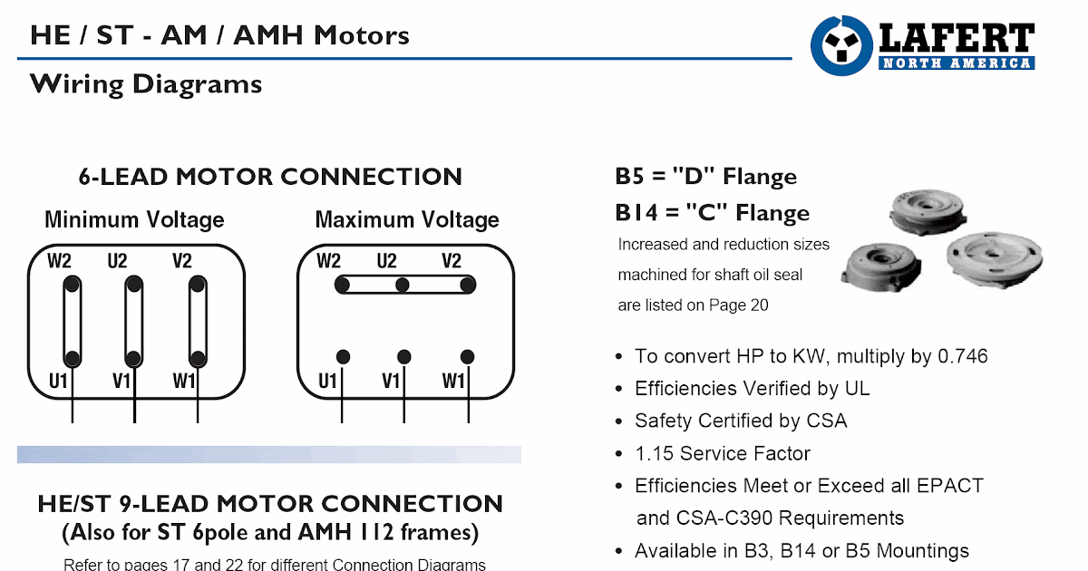
- Winding Configurations: The specific arrangement and interconnection of the 12 leads determine the motor’s winding configuration, such as delta or wye, affecting its electrical characteristics and performance.
- Speed Control: In some motors, the 12 leads allow for variable speed control by reconfiguring the winding connections, enabling the motor to operate at different speeds.
- Real-Life Examples: Motors with 12 leads are commonly used in industrial settings, such as adjustable-speed drives, conveyor systems, and pumps, where precise control and flexibility are required.
Understanding and correctly connecting the 12 leads according to the wiring diagram is crucial for the proper operation and efficiency of the motor. Incorrect lead connections can lead to motor damage, reduced performance, or even safety hazards. Therefore, it is essential for electricians and technicians to have a thorough understanding of the lead configurations and follow the specified wiring instructions carefully.
Wiring
In the context of a “480 Volt 3 Phase 12 Lead Motor Wiring Diagram,” the aspect of “Wiring: Electrical Connections” is of paramount importance as it forms the backbone of the motor’s operation and functionality.
The electrical connections within the wiring diagram specify how the motor’s internal components, such as windings, terminals, and control devices, are interconnected and connected to the external power source. These connections are crucial for ensuring proper current flow, voltage distribution, and electromagnetic field generation, which ultimately enable the motor to convert electrical energy into mechanical motion.
Real-life examples of wiring electrical connections within a 480 Volt 3 Phase 12 Lead Motor Wiring Diagram include:
- Connecting the motor’s leads to the appropriate terminals on the power source
- Establishing connections between the motor’s windings to configure the desired winding configuration (e.g., delta or wye)
- Wiring control devices, such as switches, contactors, and relays, to enable motor starting, stopping, and speed control
Understanding and correctly implementing the electrical connections outlined in the wiring diagram is essential for the safe and efficient operation of the motor. Incorrect wiring can lead to various issues, including motor damage, reduced performance, or even electrical hazards.
Terminals
In the context of a “480 Volt 3 Phase 12 Lead Motor Wiring Diagram,” terminals serve as critical connection points, establishing electrical pathways between the motor’s internal components and the external power source. These terminals are strategically positioned to facilitate the flow of current, ensuring the proper functioning and control of the motor.
The wiring diagram specifies the precise arrangement and interconnection of these terminals, guiding electricians and technicians in establishing secure and reliable electrical connections. Each terminal’s designation and function are clearly outlined, allowing for efficient troubleshooting and maintenance procedures. Real-life examples of terminals within a 480 Volt 3 Phase 12 Lead Motor Wiring Diagram include:
- Power terminals: Connect the motor to the power source, providing the electrical energy necessary for operation.
- Control terminals: Interface with external control devices, such as switches and relays, enabling remote starting, stopping, and speed adjustment of the motor.
- Ground terminals: Provide a safe electrical path to ground, protecting against electrical faults and ensuring the safety of personnel and equipment.
Understanding the significance of terminals and their proper connection is crucial for ensuring the safe and efficient operation of the motor. Incorrectly connected terminals can lead to various issues, including motor damage, reduced performance, or electrical hazards. Therefore, adhering to the specified wiring diagram and utilizing appropriate connection techniques are essential for maintaining the integrity and functionality of the electrical system.
Switches
Within a “480 Volt 3 Phase 12 Lead Motor Wiring Diagram,” switches play a vital role as control devices, enabling the safe and effective operation of the motor. These switches serve as intermediaries between the motor and external control circuits, providing the necessary means to start, stop, and regulate the motor’s operation.
The wiring diagram specifies the types and configurations of switches to be used, including their connections to the motor’s terminals and control circuits. Real-life examples of switches within a “480 Volt 3 Phase 12 Lead Motor Wiring Diagram” include:
- Power switches: Disconnect the motor from the power source, providing isolation for maintenance or emergency situations.
- Magnetic contactors: Electromagnetic switches that control the flow of current to the motor, enabling remote starting and stopping.
- Limit switches: Detect specific conditions, such as overspeed or end of travel, and trigger the motor to stop automatically.
Understanding the significance of switches as control devices in a “480 Volt 3 Phase 12 Lead Motor Wiring Diagram” is essential for ensuring the safe and efficient operation of the motor system. These switches provide essential functionality, allowing for remote control, protection against faults, and optimization of the motor’s performance.
In summary, switches play a critical role within a “480 Volt 3 Phase 12 Lead Motor Wiring Diagram” by providing control over the motor’s operation. Their inclusion enables safe and efficient motor operation, contributing to the overall functionality and reliability of the motor system.
Maintenance
In the context of “480 Volt 3 Phase 12 Lead Motor Wiring Diagram,” maintenance encompasses a range of activities crucial for ensuring the motor’s optimal performance, safety, and longevity. Regular inspection and upkeep are essential to identify potential issues, prevent breakdowns, and maintain the motor’s efficiency.
- Visual Inspection: Periodic visual inspections help detect physical damage, loose connections, or excessive wear on motor components, allowing for timely repairs.
- Electrical Testing: Electrical tests, such as insulation resistance and winding resistance measurements, assess the motor’s electrical health, identifying potential insulation breakdowns or winding faults.
- Bearing Inspection: Monitoring bearing temperatures, listening for unusual noises, and checking for excessive vibration helps identify bearing wear or misalignment, preventing catastrophic failures.
- Cleaning and Lubrication: Routine cleaning and lubrication prevent dirt, moisture, and corrosion from accumulating, reducing friction and extending the motor’s lifespan.
By adhering to a comprehensive maintenance schedule that includes regular inspections and upkeep, operators can minimize downtime, enhance safety, and ensure the reliable operation of motors within “480 Volt 3 Phase 12 Lead Motor Wiring Diagram” applications.
Troubleshooting
Within the comprehensive landscape of “480 Volt 3 Phase 12 Lead Motor Wiring Diagram,” troubleshooting emerges as a crucial aspect, empowering individuals to identify and address issues that may arise, ensuring the smooth operation and longevity of the motor system.
- Identifying Faulty Components: Troubleshooting involves systematically examining individual components, such as switches, terminals, and windings, to pinpoint the source of the malfunction.
- Interpreting Electrical Measurements: Electrical tests, such as voltage and current measurements, provide valuable insights into the motor’s electrical behavior, aiding in the identification of potential issues.
- Analyzing Operating Conditions: Real-life examples of troubleshooting include analyzing operating conditions, such as load variations or environmental factors, to determine their impact on the motor’s performance.
- Consulting Technical Documentation: Wiring diagrams and technical manuals serve as essential references during troubleshooting, providing detailed specifications and guidance for resolving specific issues.
In conclusion, troubleshooting plays a vital role in the maintenance and operation of “480 Volt 3 Phase 12 Lead Motor Wiring Diagram” systems. By identifying faulty components, interpreting electrical measurements, analyzing operating conditions, and leveraging technical documentation, individuals can effectively diagnose and resolve issues, ensuring the optimal performance and longevity of the motor system.
Safety
In the realm of “480 Volt 3 Phase 12 Lead Motor Wiring Diagram,” safety emerges as a paramount concern, as high voltage and complex electrical connections pose inherent hazards. Understanding and adhering to electrical safety guidelines are crucial to prevent accidents, injuries, and equipment damage.
The high voltage present in “480 Volt 3 Phase 12 Lead Motor Wiring Diagram” systems can cause severe electrical shocks if proper precautions are not taken. Short circuits and ground faults can lead to electrical fires and explosions, endangering personnel and property. Additionally, improper grounding and insulation can create hazardous conditions, increasing the risk of electric shock and equipment failure.
Real-life examples underscore the importance of electrical safety in “480 Volt 3 Phase 12 Lead Motor Wiring Diagram” applications. Miswiring, loose connections, and inadequate maintenance have all contributed to electrical accidents and fires in industrial and commercial settings. Understanding the potential hazards and implementing proper safety measures, such as proper grounding, circuit protection, and regular inspections, is essential to prevent these incidents.
In conclusion, “Safety: Electrical hazards” is an indispensable component of “480 Volt 3 Phase 12 Lead Motor Wiring Diagram” systems. By recognizing and mitigating electrical hazards, electricians and technicians can ensure the safe and reliable operation of these systems, preventing accidents, injuries, and costly downtime.
Efficiency
In the realm of electrical engineering, the pursuit of efficiency is paramount, and understanding the relationship between “Efficiency: Optimal performance” and “480 Volt 3 Phase 12 Lead Motor Wiring Diagram” holds immense significance. Efficiency, in this context, refers to the ability of the motor system to convert electrical energy into mechanical energy with minimal losses.
A “480 Volt 3 Phase 12 Lead Motor Wiring Diagram” outlines the electrical connections and configurations necessary for the proper operation of a three-phase motor. Optimal performance is directly tied to the accuracy and precision of these connections, as any deviations can lead to energy inefficiencies and reduced motor lifespan. Real-life examples abound, where improper wiring has resulted in excessive energy consumption, overheating, and premature motor failure.
The practical applications of understanding the connection between efficiency and wiring diagrams are far-reaching. In industrial settings, where motors are the backbone of production machinery, maximizing efficiency translates to reduced operating costs and increased productivity. Energy-efficient motors, coupled with optimized wiring diagrams, contribute to a greener and more sustainable manufacturing environment.
In summary, “Efficiency: Optimal performance” is a cornerstone of “480 Volt 3 Phase 12 Lead Motor Wiring Diagram” systems. By adhering to precise wiring configurations, engineers and technicians can harness the full potential of electrical motors, ensuring peak performance, energy conservation, and extended equipment longevity.

![asrhanyrny [15+] 480v 3 Phase Motor Wiring Diagram, 480V 3 Phase 6](https://i0.wp.com/www.practicalmachinist.com/vb/attachments/f11/176839d1469929141-18-wire-2-speed-dual-voltage-motor-puzzler-18wire2speed.jpg?w=665&ssl=1)


Related Posts