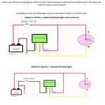
Spektrum Receiver Wiring Diagram
A Spektrum receiver wiring diagram is an electrical schematic that details the connections and wiring required to establish communication between a Spektrum receiver and other electronic components, such as a flight controller, motor, or battery.
Importance, Benefits, and Historical Context
- Ensures proper functioning and compatibility of Spektrum receivers and connected devices.
- Simplifies the installation and troubleshooting process by providing a visual guide to the wiring connections.
- Key historical development: Standardization of Spektrum receiver wiring diagrams across different models and generations.
Transition to Main Article Topics
This article will delve deeper into the components of a Spektrum receiver wiring diagram, how to interpret and use it effectively, and troubleshoot common wiring issues.
Essential Aspects of Spektrum Receiver Wiring Diagrams
Spektrum receiver wiring diagrams play a crucial role in the installation and maintenance of Spektrum receivers. Understanding their key aspects is essential for proper functioning and troubleshooting. Here are nine key aspects to consider:
- Purpose: Outlines the electrical connections between a Spektrum receiver and other components.
- Components: Includes symbols representing the receiver, battery, servos, and other connected devices.
- Wiring: Specifies the type and color of wires used for each connection.
- Signal Flow: Indicates the direction of signal transmission between components.
- Power Distribution: Shows how power is supplied from the battery to the receiver and connected devices.
- Channel Assignments: Identifies which receiver channels are assigned to specific servos or other devices.
- Fail-Safe Settings: Documents the fail-safe settings programmed into the receiver.
- Compatibility: Ensures compatibility between the receiver and other components based on voltage, protocol, and connector types.
- Safety: Provides guidelines for proper wiring to prevent short circuits, overloads, and other hazards.
These aspects are interconnected and essential for understanding the functionality and proper use of Spektrum receiver wiring diagrams. They serve as a guide for installation, troubleshooting, and ensuring the reliable operation of radio control systems.
Purpose
The purpose of a Spektrum receiver wiring diagram is to provide a clear and concise representation of the electrical connections required between a Spektrum receiver and other electronic components in a radio control system. Without this diagram, it would be difficult to know which wires connect to which terminals on the receiver, potentially leading to incorrect or unsafe operation.
A Spektrum receiver wiring diagram is a critical component of ensuring that all components in a radio control system are properly connected and functioning correctly. By understanding the purpose and contents of a Spektrum receiver wiring diagram, users can confidently assemble and maintain their radio control systems, reducing the risk of errors and ensuring reliable performance.
Real-life examples of the purpose of a Spektrum receiver wiring diagram include:
- Providing instructions on how to connect a Spektrum receiver to a flight controller in a multirotor drone.
- Guiding the installation of a Spektrum receiver in a radio-controlled car or boat.
- Assisting in the troubleshooting of connection issues between a Spektrum receiver and other components.
Understanding the purpose of a Spektrum receiver wiring diagram is essential for anyone who wants to use Spektrum receivers in their radio control systems. By following the diagram carefully, users can ensure that their systems are connected correctly and operating safely.
Components
The components included in a Spektrum receiver wiring diagram play a crucial role in understanding the connections and functionality of the system. These symbols represent the physical components that are connected to the receiver, including the receiver itself, the battery, servos, and any other devices that are part of the radio control system.
The connection between these components and the Spektrum receiver wiring diagram is essential because it provides a visual representation of how the system is assembled and how the components interact with each other. Without this diagram, it would be difficult to know which wires connect to which terminals on the receiver, potentially leading to incorrect or unsafe operation.
Real-life examples of the components included in a Spektrum receiver wiring diagram include:
- The Spektrum receiver itself, which is the central component of the radio control system and receives signals from the transmitter.
- The battery, which provides power to the receiver and other components.
- Servos, which are used to control the movement of the control surfaces on the aircraft or vehicle.
- Other devices, such as ESCs (electronic speed controllers) or flight controllers, which may be connected to the receiver to provide additional functionality.
Understanding the components included in a Spektrum receiver wiring diagram is essential for anyone who wants to use Spektrum receivers in their radio control systems. By understanding the purpose and function of each component, users can ensure that their systems are connected correctly and operating safely.
Wiring
Wiring, as specified in a Spektrum receiver wiring diagram, holds paramount importance in ensuring the proper functionality and safety of a radio control system. It outlines the specific type and color of wires to be used for each connection, providing a clear and concise guide for assembling and maintaining the system.
- Wire Types: The diagram specifies the type of wire required for each connection, such as servo wire, power wire, or signal wire. This ensures that the correct wire gauge and insulation are used, which is crucial for maintaining signal integrity and preventing electrical hazards.
- Color Coding: The diagram assigns specific colors to different wire types or functions. This color coding simplifies the identification of wires during installation and troubleshooting, reducing the risk of errors and ensuring proper connections.
- Connector Compatibility: The diagram takes into account the compatibility of connectors used in the system. It specifies the type of connectors required for each wire, such as JST, Futaba, or Molex connectors. Matching the correct connectors ensures secure and reliable connections.
- Signal Integrity: The diagram considers signal integrity by specifying the use of shielded or twisted-pair wires for critical connections. These types of wires minimize electromagnetic interference, ensuring that signals are transmitted accurately and without distortion.
Adhering to the wiring specifications provided in the Spektrum receiver wiring diagram is essential for the safe and efficient operation of the radio control system. By using the correct wire types, color coding, and connectors, users can minimize the risk of electrical problems, ensure reliable signal transmission, and extend the lifespan of their components.
Signal Flow
Signal flow, as depicted in a Spektrum receiver wiring diagram, plays a vital role in understanding how signals are transmitted between components in a radio control system. This aspect of the diagram provides a visual representation of the signal paths, ensuring that components communicate effectively and reliably.
- Signal Paths: The diagram clearly outlines the signal paths between the receiver and other components, such as servos, ESCs, and flight controllers. This helps identify the flow of control signals, power distribution, and sensor data throughout the system.
- Signal Types: The diagram distinguishes between different types of signals, such as analog, digital, and PWM (pulse-width modulation). Understanding the signal types is crucial for selecting appropriate wires and connectors, ensuring signal integrity and minimizing interference.
- Signal Direction: The diagram indicates the direction of signal flow, which is essential for proper component orientation and connection. It specifies which components are transmitting signals and which are receiving them, ensuring that signals are routed correctly.
- Signal Integrity: The diagram considers factors that affect signal integrity, such as wire shielding, grounding, and noise reduction techniques. By adhering to these guidelines, users can minimize signal loss, distortion, and interference, ensuring reliable communication between components.
Overall, understanding signal flow in a Spektrum receiver wiring diagram is crucial for ensuring proper system operation. By following the signal paths, identifying signal types, and considering signal integrity, users can assemble and maintain radio control systems that function efficiently and reliably.
Power Distribution
The power distribution aspect of a Spektrum Receiver Wiring Diagram is a critical component, outlining the electrical connections and pathways for supplying power from the battery to the receiver and all connected devices. Understanding this aspect is essential for ensuring reliable and safe operation of the entire radio control system.
The Spektrum Receiver Wiring Diagram specifies the type and gauge of wires required for power distribution, ensuring that adequate current capacity is provided to power all components without excessive voltage drop or overheating. It also indicates the proper polarity of connections, preventing damage to components due to reversed polarity.
Real-life examples of power distribution in a Spektrum Receiver Wiring Diagram include:
- Specifying the wire gauge and type for connecting the battery to the receiver, ensuring that sufficient current can be supplied to power the receiver and connected devices.
- Indicating the polarity of the power connections, ensuring that the positive and negative terminals of the battery are correctly connected to the receiver.
- Outlining the connections for powering additional devices, such as servos, ESCs, or flight controllers, ensuring that they receive the appropriate voltage and current.
Understanding the power distribution aspect of a Spektrum Receiver Wiring Diagram allows users to properly connect and power their radio control systems. By following the diagram carefully, users can avoid incorrect or unsafe connections that could lead to component damage or system malfunctions.
In conclusion, the power distribution aspect of a Spektrum Receiver Wiring Diagram is crucial for ensuring the proper functioning and safety of a radio control system. By understanding the connections and pathways for power distribution, users can confidently assemble and maintain their systems, ensuring reliable and efficient operation.
Channel Assignments
Channel assignments, as defined in a Spektrum Receiver Wiring Diagram, play a crucial role in establishing the communication and control between the receiver and various components within a radio control system. This aspect of the wiring diagram outlines the specific receiver channels that are designated to control specific servos, ESCs, or other devices.
The importance of channel assignments lies in ensuring proper functionality and coordination of the radio control system. Each channel on the receiver corresponds to a specific control function, such as throttle, aileron movement, or rudder control. By assigning the correct channels to the appropriate devices, the user can ensure that the transmitter inputs are accurately translated into the desired control actions.
Real-life examples of channel assignments within a Spektrum Receiver Wiring Diagram include:
- Assigning channel 1 to control the throttle servo, enabling the user to control the speed or power of the motor or engine.
- Assigning channel 2 to control the aileron servos, allowing the user to control the left and right rolling motion of the aircraft.
- Assigning channel 4 to control the rudder servo, providing the user with the ability to control the yaw or side-to-side movement of the aircraft.
Understanding channel assignments is essential for users to correctly set up and operate their radio control systems. By matching the correct channels to the intended functions, users can achieve precise and responsive control over their models.
In conclusion, channel assignments in a Spektrum Receiver Wiring Diagram are critical for establishing the communication and control architecture of a radio control system. Proper channel assignments ensure that the transmitter inputs are accurately translated into the desired control actions, enabling users to operate their models with precision and confidence.
Fail-Safe Settings
The connection between “Fail-Safe Settings: Documents the fail-safe settings programmed into the receiver.” and “Spektrum Receiver Wiring Diagram” lies in the critical role fail-safe settings play within the overall functionality of a Spektrum receiver. A Spektrum Receiver Wiring Diagram outlines the electrical connections and configuration of the receiver, including the programming of fail-safe settings.
Fail-safe settings are essential for ensuring the safe operation of radio control systems. They define the actions that the receiver will take in the event of a signal loss or interruption from the transmitter. By documenting these settings within the Spektrum Receiver Wiring Diagram, users can ensure that their systems are configured to respond appropriately to signal loss, minimizing the risk of accidents or damage.
Real-life examples of fail-safe settings within a Spektrum Receiver Wiring Diagram include:
- Setting the throttle channel to a predefined position in the event of signal loss, preventing uncontrolled acceleration or deceleration.
- Programming the control surfaces to move to a neutral or safe position, ensuring stability and preventing erratic movements.
- Activating a failsafe mode that limits the range of control inputs, reducing the risk of over-controlling or exceeding the physical limits of the model.
Understanding the connection between “Fail-Safe Settings: Documents the fail-safe settings programmed into the receiver.” and “Spektrum Receiver Wiring Diagram” is crucial for users to ensure the safety and reliability of their radio control systems. By correctly programming and documenting fail-safe settings, users can minimize the risks associated with signal loss and enhance the overall performance and safety of their models.
In conclusion, the “Fail-Safe Settings: Documents the fail-safe settings programmed into the receiver.” aspect of a Spektrum Receiver Wiring Diagram plays a vital role in ensuring the safe and reliable operation of radio control systems. It provides users with the ability to define the receiver’s behavior in the event of signal loss, preventing accidents and damage. Understanding this connection is essential for users to confidently operate their models and maintain a high level of safety.
Compatibility
The connection between “Compatibility: Ensures compatibility between the receiver and other components based on voltage, protocol, and connector types.” and “Spektrum Receiver Wiring Diagram” is crucial because compatibility is a fundamental aspect of the wiring diagram’s function. A Spektrum Receiver Wiring Diagram outlines the electrical connections and configuration of the receiver, ensuring that the receiver is compatible with other components in the radio control system, such as servos, ESCs, and flight controllers.
The cause and effect relationship between “Compatibility: Ensures compatibility between the receiver and other components based on voltage, protocol, and connector types.” and “Spektrum Receiver Wiring Diagram” is evident in the following ways:
- Voltage Compatibility: The wiring diagram specifies the voltage range that the receiver can handle. This information is critical for ensuring that the receiver is connected to a compatible power source, such as a battery or BEC (Battery Eliminator Circuit).
- Protocol Compatibility: The wiring diagram indicates the communication protocol used by the receiver. This information is crucial for ensuring that the receiver can communicate effectively with other components, such as the transmitter and flight controller.
- Connector Compatibility: The wiring diagram specifies the types of connectors used by the receiver. This information is essential for selecting the appropriate cables and accessories to connect the receiver to other components.
Real-life examples of “Compatibility: Ensures compatibility between the receiver and other components based on voltage, protocol, and connector types.” within “Spektrum Receiver Wiring Diagram” include:
- Specifying that the receiver is compatible with 1S-3S LiPo batteries, ensuring that the receiver can be used with a wide range of battery configurations.
- Indicating that the receiver uses the Spektrum DSMX protocol, ensuring that it can communicate with Spektrum transmitters and other DSMX-compatible devices.
- Outlining that the receiver uses standard JR/Futaba-style connectors, ensuring that it can be easily connected to servos, ESCs, and other components that use the same connector type.
Understanding the practical applications of “Compatibility: Ensures compatibility between the receiver and other components based on voltage, protocol, and connector types.” within “Spektrum Receiver Wiring Diagram” is essential for users to ensure the proper functioning and safety of their radio control systems. By carefully following the compatibility guidelines provided in the wiring diagram, users can avoid incorrect or unsafe connections that could lead to component damage or system malfunctions.
In conclusion, the “Compatibility: Ensures compatibility between the receiver and other components based on voltage, protocol, and connector types.” aspect of a Spektrum Receiver Wiring Diagram plays a vital role in ensuring the successful assembly and operation of radio control systems. It provides users with the information they need to make informed decisions about component selection and connections, ensuring that all components are compatible and functioning properly.
Safety
Within a Spektrum Receiver Wiring Diagram, the safety aspect plays a critical role in outlining proper wiring practices to prevent potential hazards, ensuring the safe and reliable operation of the radio control system. These guidelines provide crucial instructions for users to follow during the assembly and maintenance of their systems.
The cause and effect relationship between “Safety: Provides guidelines for proper wiring to prevent short circuits, overloads, and other hazards” and “Spektrum Receiver Wiring Diagram” is evident in the following ways:
- By providing clear instructions for wiring connections, the diagram helps prevent incorrect or unsafe practices that could lead to short circuits, overloads, or other electrical hazards.
- The diagram specifies the appropriate wire gauges and types to be used, ensuring that the wires can handle the current draw of the connected components without overheating or causing damage.
- It outlines the proper insulation and shielding techniques to prevent electrical interference and ensure reliable signal transmission.
Real-life examples of “Safety: Provides guidelines for proper wiring to prevent short circuits, overloads, and other hazards” within “Spektrum Receiver Wiring Diagram” include:
- Indicating the use of heat shrink tubing to insulate and protect wire connections, preventing short circuits.
- Specifying the correct wire gauge for high-current applications, such as connecting the battery to the receiver, to prevent overheating.
- Outlining the use of ferrite beads or capacitors for noise suppression, minimizing electrical interference and ensuring reliable communication.
Understanding the practical applications of “Safety: Provides guidelines for proper wiring to prevent short circuits, overloads, and other hazards” within “Spektrum Receiver Wiring Diagram” is essential for users to ensure the safety and longevity of their radio control systems. By carefully following the safety guidelines provided in the wiring diagram, users can minimize the risk of electrical problems and accidents.
In conclusion, the “Safety: Provides guidelines for proper wiring to prevent short circuits, overloads, and other hazards” aspect of a Spektrum Receiver Wiring Diagram is a critical component for ensuring the safe and reliable operation of radio control systems. It provides users with the necessary instructions and guidelines to assemble and maintain their systems correctly, minimizing the potential for electrical hazards and ensuring the longevity of their equipment.


Related Posts