An audio jack wiring diagram depicts the arrangement of wires and connections within an audio jack, outlining the specific wiring scheme for transmitting audio signals efficiently. It serves as a guide for installing, troubleshooting, and understanding how different audio connectors work.
Audio jack wiring diagrams are crucial because they ensure proper signal flow and prevent issues like noise, distortion, or intermittent connections. They also facilitate standardized connections, enabling compatibility between various audio devices. Historically, the development of balanced audio connections with TRS (Tip, Ring, Sleeve) plugs was a significant advancement, reducing signal loss and interference.
This article will explore different types of audio jack wiring diagrams, their applications in various audio systems, and the essential considerations for selecting the right wiring scheme for specific requirements.
Understanding the essential aspects of “Audio Jack Wiring Diagram” is crucial for effectively grasping its concept and applications. These aspects encompass various dimensions related to the wiring scheme, including its components, functionality, and significance.
- Wiring Configuration: Outlines the specific arrangement of wires and connections within an audio jack, determining the signal flow and compatibility.
- Connector Types: Covers the different types of audio connectors used in various applications, such as TRS (Tip, Ring, Sleeve), XLR, and RCA.
- Signal Flow: Explains the path of audio signals through the jack’s wiring, including input and output connections.
- Balanced vs. Unbalanced Connections: Describes the two main types of audio connections, highlighting their advantages and disadvantages.
- Shielding and Noise Reduction: Discusses techniques used to minimize noise and interference in audio signals.
- Troubleshooting: Provides guidance on identifying and resolving common issues related to audio jack wiring.
- Compatibility: Explores the importance of matching wiring diagrams to ensure compatibility between different audio devices.
- Safety Considerations: Highlights potential electrical hazards and safety measures to consider when working with audio jack wiring.
- Applications: Examines the diverse applications of audio jack wiring diagrams in various audio systems, from home audio to professional sound reinforcement.
- Historical Evolution: Traces the development of audio jack wiring diagrams, including the introduction of standardized connectors and advancements in audio technology.
These aspects provide a comprehensive understanding of audio jack wiring diagrams, enabling effective installation, maintenance, and troubleshooting of audio systems. They serve as a foundation for further exploration of specific wiring schemes and their applications in different audio contexts.
Wiring Configuration
The wiring configuration of an audio jack forms the foundation of an audio jack wiring diagram. It defines the precise layout and connection of wires within the jack, determining how audio signals flow and the compatibility of the jack with different devices.
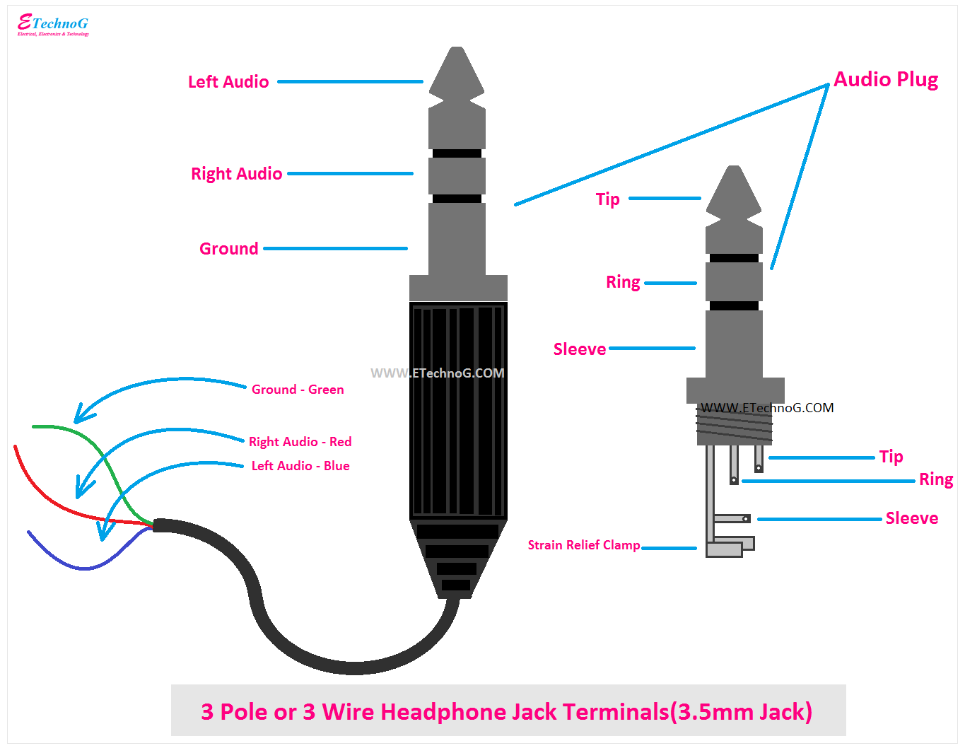
For instance, a three-conductor TRS (Tip, Ring, Sleeve) jack commonly used for stereo audio applications, has a specific wiring configuration where the tip carries the left channel signal, the ring carries the right channel signal, and the sleeve serves as the ground connection. This configuration ensures proper signal routing and compatibility with TRS-equipped devices.
Understanding wiring configurations is crucial for correctly installing, troubleshooting, and maintaining audio systems. By adhering to the designated wiring scheme, audio professionals can ensure optimal signal transmission, minimize noise and interference, and achieve desired audio performance.
Furthermore, the ability to interpret and work with audio jack wiring diagrams is essential in various practical applications. From connecting home audio systems to installing professional sound reinforcement equipment, a thorough understanding of wiring configurations empowers technicians and enthusiasts alike to achieve reliable and high-quality audio experiences.
Connector Types
Understanding the types of audio connectors is essential in the context of audio jack wiring diagrams. These connectors establish the physical interface between audio devices and cables, enabling signal transmission and compatibility. Here are four key facets of connector types:
- Connector Design: Audio connectors come in various shapes and sizes, each designed for specific applications. TRS (Tip, Ring, Sleeve) connectors are commonly used for stereo audio, while XLR connectors are standard in professional audio setups, and RCA connectors are widely employed in home audio systems.
- Signal Configuration: Connectors can be designed for different signal configurations. TRS connectors, for example, can carry balanced or unbalanced signals, while RCA connectors typically handle unbalanced signals. Understanding the signal configuration of a connector is crucial for proper wiring and signal integrity.
- Durability and Reliability: Audio connectors must withstand frequent use and handling. Different types of connectors offer varying levels of durability and reliability. XLR connectors, with their locking mechanism, are renowned for their robustness, making them suitable for demanding live sound applications.
- Compatibility: Ensuring compatibility between connectors is vital. Mismatched connectors can result in poor signal transmission or damage to equipment. Audio jack wiring diagrams specify the types of connectors required for each connection, ensuring compatibility and proper functionality.
Comprehending connector types is fundamental to effectively utilizing audio jack wiring diagrams. By understanding the design, signal configuration, durability, and compatibility of different connectors, audio professionals can make informed decisions when selecting and using audio connectors, ensuring optimal audio performance and system reliability.
Signal Flow
Within the realm of “Audio Jack Wiring Diagram”, understanding signal flow is paramount. It unravels the intricate journey of audio signals as they traverse through the jack’s wiring, delineating the pathways from input to output. This aspect holds immense significance in deciphering the functionality and behavior of audio systems.
- Input and Output Connections: Audio jack wiring diagrams meticulously detail the designated input and output connections for each jack. Input connections receive audio signals from external sources, while output connections transmit signals to downstream devices or components. Identifying these connections is crucial for ensuring proper signal flow and system connectivity.
- Signal Routing: Wiring diagrams illustrate the specific paths that audio signals take within the jack’s wiring. They indicate the connections between individual wires and terminals, ensuring that signals reach their intended destinations. Understanding signal routing is essential for troubleshooting and maintaining audio systems.
- Signal Integrity: Signal flow diagrams also provide insights into factors that can affect signal integrity, such as noise, interference, and impedance matching. Proper wiring practices and component selection can help minimize signal degradation and preserve audio quality.
- Grounding: Audio jack wiring diagrams often include grounding connections, which serve as a reference point for audio signals. Proper grounding techniques help reduce noise and ensure system stability. Understanding grounding principles is crucial for achieving optimal audio performance.
By unraveling the intricacies of signal flow through audio jack wiring diagrams, audio professionals gain a deeper comprehension of audio system operation. This knowledge empowers them to design, install, and maintain audio systems that deliver pristine sound quality and reliable performance.
Balanced vs. Unbalanced Connections
The concepts of “Balanced vs. Unbalanced Connections” and “Audio Jack Wiring Diagram” are intricately intertwined, as the choice of connection type directly influences the wiring scheme and overall performance of an audio system. Balanced connections offer superior noise rejection compared to unbalanced connections, making them the preferred choice for professional audio applications where signal integrity is paramount.
In an unbalanced connection, the audio signal is carried on a single wire, with a ground wire serving as a reference. This simplicity makes unbalanced connections easy to implement and widely used in consumer electronics. However, unbalanced connections are susceptible to noise and interference, especially over long cable runs.
Balanced connections, on the other hand, employ three wires: two signal wires and a ground wire. The signal wires carry the same audio signal but with opposite polarity, effectively canceling out any noise or interference picked up by the cable. This inherent noise rejection makes balanced connections ideal for professional audio environments where long cable runs and high signal levels are common.
Audio jack wiring diagrams must account for the type of connection being used. Balanced connections require specific wiring configurations to maintain the signal polarity and achieve the desired noise cancellation. TRS (Tip, Ring, Sleeve) connectors are commonly used for balanced connections, with the tip and ring carrying the balanced signal and the sleeve serving as the ground reference.
Understanding the differences between balanced and unbalanced connections, and their impact on audio jack wiring diagrams, is crucial for achieving optimal audio performance. Balanced connections are essential in professional audio applications where noise reduction and signal integrity are critical, while unbalanced connections remain widely used in consumer electronics due to their simplicity and cost-effectiveness.
Shielding and Noise Reduction
In the realm of audio jack wiring diagrams, “Shielding and Noise Reduction” stands as a cornerstone, influencing the design and implementation of audio systems. Shielding techniques play a crucial role in mitigating noise and interference, ensuring the integrity and fidelity of audio signals.
Noise and interference in audio signals can originate from various sources, including electromagnetic radiation, ground loops, and crosstalk. Shielding involves employing conductive materials to create a protective barrier around audio cables and components. This barrier effectively blocks or redirects unwanted signals, preventing them from corrupting the audio signal.
Audio jack wiring diagrams often incorporate shielding techniques to achieve optimal noise reduction. Coaxial cables, commonly used in audio applications, feature a central conductor surrounded by a braided shield. The shield acts as a Faraday cage, preventing external electromagnetic interference from reaching the inner conductor.
In addition to cable shielding, grounding techniques also play a vital role in noise reduction. Proper grounding provides a low-impedance path for unwanted currents to dissipate, preventing them from interfering with audio signals. Audio jack wiring diagrams often specify grounding connections, ensuring that components are correctly grounded and shielded to minimize noise.
Understanding shielding and noise reduction techniques is essential for designing and maintaining high-quality audio systems. By incorporating effective shielding measures into audio jack wiring diagrams, audio professionals can significantly reduce noise and interference, resulting in pristine audio quality and reliable system performance.
Troubleshooting
The ability to troubleshoot audio jack wiring is a valuable skill for maintaining high-quality audio systems. Troubleshooting involves identifying the source of a problem and implementing appropriate solutions to restore proper functionality. Audio jack wiring diagrams play a crucial role in this process, providing a roadmap for tracing connections and identifying potential issues.
- Identifying Loose Connections: Loose connections can introduce intermittent audio problems, crackling noises, or complete signal loss. Troubleshooting involves physically inspecting the jack and cable connections, ensuring that they are secure and making good contact.
- Testing for Continuity: Continuity testing verifies that the electrical path between two points in the wiring is complete. Using a multimeter, technicians can check for continuity between the jack’s terminals and the corresponding points on the connected device. Broken or damaged wires can be identified and replaced.
- Grounding Issues: Improper grounding can cause humming, buzzing, or other noise artifacts. Troubleshooting involves checking that the jack and its connected components are properly grounded to a common reference point. This may require verifying the continuity of ground connections or addressing ground loops.
- Signal Interference: External electromagnetic interference can disrupt audio signals, resulting in noise or signal degradation. Troubleshooting involves identifying potential sources of interference, such as nearby power lines or other electronic devices, and implementing shielding or isolation techniques to minimize their impact.
By understanding the principles of troubleshooting and utilizing audio jack wiring diagrams, technicians can effectively diagnose and resolve common issues related to audio jack wiring. This ensures that audio systems operate reliably, deliver optimal sound quality, and provide an enjoyable listening experience.
Compatibility
Within the realm of “Audio Jack Wiring Diagram”, compatibility assumes paramount importance. Matching wiring diagrams is essential to ensure seamless interoperability between diverse audio devices, enabling the creation of robust and functional audio systems.
Audio devices come in a myriad of shapes, sizes, and functionalities. Each device has a unique wiring configuration, dictating how audio signals are transmitted and received. Mismatched wiring diagrams can lead to incorrect signal routing, noise, distortion, or even device damage. By adhering to the designated wiring scheme, audio professionals can guarantee that devices are properly connected and operating in harmony.
Real-life examples abound, underscoring the significance of compatibility in audio jack wiring diagrams. Consider a scenario where a professional sound engineer is tasked with connecting a mixing console to a power amplifier. Mismatching the wiring diagrams could result in incorrect signal routing, leading to distorted or inaudible audio output. Conversely, proper wiring ensures that the audio signals flow smoothly from the console to the amplifier, delivering pristine sound to the audience.
The practical applications of compatibility in audio jack wiring diagrams extend far beyond professional audio setups. In home audio systems, matching wiring diagrams is crucial for connecting components such as CD players, receivers, and speakers. Correct wiring ensures optimal signal transfer, resulting in a high-quality listening experience. Moreover, compatibility is essential in the installation of car audio systems, where mismatched wiring can lead to safety hazards or poor sound performance.
Understanding the importance of compatibility in audio jack wiring diagrams empowers individuals to design, install, and maintain audio systems with confidence. By meticulously matching wiring diagrams, audio enthusiasts and professionals alike can ensure seamless connectivity, optimal signal transmission, and exceptional audio performance.
Safety Considerations
In the domain of “Audio Jack Wiring Diagram”, safety considerations emerge as a critical aspect, ensuring the well-being of individuals and the integrity of audio systems. Understanding and adhering to safety measures are paramount to prevent electrical hazards and maintain optimal system performance.
Electrical hazards in audio jack wiring primarily stem from improper handling, faulty components, or incorrect connections. These hazards can manifest as electric shocks, short circuits, or even fires, posing significant risks to both individuals and equipment. Audio jack wiring diagrams serve as essential safety guides, providing detailed instructions on proper wiring techniques and safety precautions.
As a real-life example, consider the scenario of connecting an audio jack to a power outlet. Mismatched wiring or loose connections could lead to a short circuit, potentially causing damage to the equipment or electrical fires. The wiring diagram for this specific connection would clearly outline the correct wiring sequence and safety measures, such as using insulated wires and ensuring secure connections.
The practical applications of understanding safety considerations in audio jack wiring diagrams extend beyond preventing electrical hazards. Proper wiring also ensures optimal signal transmission, minimizes noise and interference, and prolongs the lifespan of audio equipment. By following safety guidelines and adhering to the designated wiring scheme, audio professionals and enthusiasts can create safe and reliable audio systems that deliver high-quality sound.
In summary, safety considerations play a pivotal role in “Audio Jack Wiring Diagram”, safeguarding individuals from electrical hazards and ensuring the integrity of audio systems. Wiring diagrams serve as indispensable tools, providing clear instructions and safety guidelines for proper wiring techniques. Understanding and adhering to these safety measures are essential for the safe and successful installation, maintenance, and operation of audio systems.
Applications
Within the realm of “Audio Jack Wiring Diagram”, the exploration of applications unveils the practical significance and versatility of these diagrams across diverse audio systems. They serve as blueprints for connecting audio components, ensuring optimal signal transmission and system performance in a myriad of settings.
- Home Audio: Audio jack wiring diagrams guide the installation and configuration of home audio systems. From connecting speakers to receivers and CD players, these diagrams ensure proper signal routing and system compatibility, resulting in a seamless and enjoyable listening experience.
- Professional Audio: In professional sound reinforcement applications, audio jack wiring diagrams play a critical role in connecting mixers, amplifiers, and other equipment. They enable precise signal routing and level matching, ensuring clear and balanced audio reproduction in venues such as concert halls and theaters.
- Headphone and Microphone Connections: Audio jack wiring diagrams are essential for understanding and troubleshooting headphone and microphone connections. They provide insights into the wiring scheme of different types of jacks and connectors, ensuring compatibility and optimal audio quality during recording and playback.
- Instrument Cables: Audio jack wiring diagrams are indispensable for designing and repairing instrument cables used to connect musical instruments to amplifiers and effects pedals. By understanding the wiring configuration of instrument jacks, musicians can create custom cables tailored to their specific needs and ensure reliable signal transmission.
The applications of audio jack wiring diagrams extend far beyond these core areas, encompassing various other audio systems and scenarios. Their ability to facilitate efficient and reliable signal transmission makes them indispensable tools for audio engineers, musicians, and enthusiasts alike. Understanding and utilizing these diagrams empowers individuals to create high-quality audio systems that deliver exceptional sound and performance.
Historical Evolution
The historical evolution of audio jack wiring diagrams is inextricably intertwined with the development of audio technology as a whole. As audio equipment became more sophisticated, the need for standardized wiring schemes arose to ensure compatibility and optimal signal transmission.
A pivotal moment in this evolution was the introduction of standardized connectors, such as the 3.5 mm TRS (Tip, Ring, Sleeve) jack. This connector became ubiquitous in consumer audio devices, enabling easy and reliable connections between headphones, microphones, and other audio peripherals.
Furthermore, advancements in audio technology led to the development of new wiring configurations and specialized connectors. For instance, the advent of balanced audio connections, using TRS connectors, significantly reduced noise and interference in professional audio applications.
Understanding the historical evolution of audio jack wiring diagrams provides valuable insights into the design and implementation of modern audio systems. By tracing the development of standardized connectors and advancements in audio technology, audio professionals can appreciate the evolution of industry best practices and make informed decisions when working with audio jack wiring.
In summary, the historical evolution of audio jack wiring diagrams is a testament to the ongoing progress in audio technology. The introduction of standardized connectors and advancements in audio technology have shaped the way we connect and transmit audio signals, leading to improved sound quality, reliability, and compatibility in audio systems.


Related Posts


