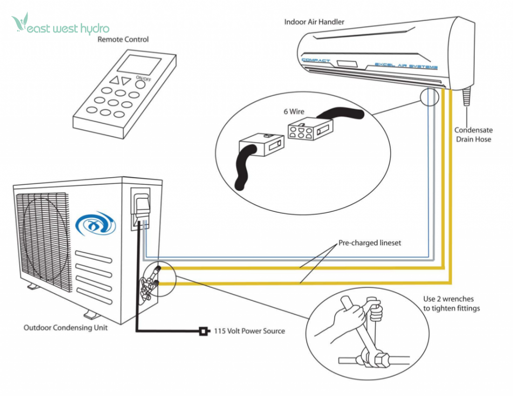
A “110v Mini Split Wiring Diagram” is a detailed plan elucidating the electrical connections for a mini-split system, typically powering it with a standard 110-volt electrical outlet. For instance, a common home application involves connecting the indoor unit to the outdoor unit via a conduit carrying electrical wires, a refrigerant line, and a condensate drain line, as per the diagram’s instructions.
This diagram is crucial for safe and efficient system operation. It ensures proper polarity, grounding, and wire sizing to avoid electrical hazards and optimize performance. One of the key historical developments in mini-split technology was the advent of 110-volt models, which expanded their accessibility to homes and businesses with limited electrical capacity.
This article delves into the intricacies of 110v Mini Split Wiring Diagrams, exploring their components, installation guidelines, troubleshooting techniques, and safety precautions. It aims to empower homeowners, contractors, and technicians with the knowledge and understanding to confidently navigate the electrical aspects of mini-split systems.
Understanding the essential aspects of “110v Mini Split Wiring Diagram” is crucial for safe and efficient installation and operation of mini-split systems. These aspects encompass various dimensions, including:
- Circuit Requirements
- Wire Sizing
- Polarity
- Grounding
- Conduit Type
- Refrigerant Line
- Condensate Drain
- Safety Precautions
- Troubleshooting
These aspects are interconnected and play vital roles in ensuring the proper functioning of the mini-split system. For instance, correct wire sizing prevents overheating and potential fire hazards, while proper grounding protects against electrical shocks. Understanding the refrigerant line and condensate drain requirements ensures efficient cooling and prevents water damage. Safety precautions, such as following electrical codes and using appropriate tools, are paramount to avoid accidents during installation and maintenance.
Circuit Requirements
In the context of “110v Mini Split Wiring Diagram”, “Circuit Requirements” dictate the electrical infrastructure necessary to safely and efficiently power the mini-split system. These requirements encompass various considerations, including:
- Dedicated Circuit: Each mini-split system requires a dedicated electrical circuit to prevent overloading and potential electrical hazards. This dedicated circuit should be sized appropriately based on the system’s power consumption and should not be shared with other appliances or devices.
- Circuit Breaker: The dedicated circuit should be protected by a circuit breaker rated for the maximum amperage of the mini-split system. The circuit breaker acts as a safety device, tripping to interrupt the flow of electricity in case of a fault or overload.
- Wire Gauge: The electrical wires used in the circuit must be of sufficient gauge to handle the current draw of the mini-split system. Using wires that are too thin can lead to overheating and potential fire hazards.
- Grounding: Proper grounding is essential for the safe operation of any electrical system, including mini-split systems. The ground wire provides a path for fault currents to safely flow to the ground, protecting against electrical shocks and damage to equipment.
Understanding and adhering to the “Circuit Requirements” specified in the “110v Mini Split Wiring Diagram” are crucial for ensuring the safe and efficient operation of the mini-split system. Neglecting these requirements can lead to a variety of issues, including tripped circuit breakers, overheating, reduced system performance, and even electrical fires. By carefully following the wiring diagram and meeting the circuit requirements, homeowners and technicians can ensure that their mini-split system operates reliably and safely for years to come.
Wire Sizing
In the realm of “110v Mini Split Wiring Diagram”, “Wire Sizing” plays a pivotal role in ensuring the safe and efficient operation of the mini-split system. Proper wire sizing involves selecting electrical wires with the appropriate cross-sectional area to handle the current draw of the system without overheating or causing voltage drop.
- Ampacity: Ampacity refers to the maximum amount of current that a wire can safely carry without overheating. When selecting wires for a 110v mini-split system, it is crucial to choose wires with an ampacity that exceeds the maximum current draw of the system.
- Voltage Drop: Voltage drop is the reduction in voltage that occurs when current flows through a wire. Excessive voltage drop can lead to reduced system performance and potential damage to equipment. Proper wire sizing helps minimize voltage drop and ensures that the mini-split system receives the appropriate voltage.
- Wire Gauge: Wire gauge is a standardized system for specifying the diameter of electrical wires. The lower the wire gauge number, the thicker the wire and the higher its ampacity. For 110v mini-split systems, the wire gauge should be selected based on the ampacity requirements and the length of the wire run.
- Conduit: In some cases, wires for a 110v mini-split system may need to be run through a conduit, which is a protective pipe or tube. The size of the conduit should be appropriate for the number and size of wires being run through it, ensuring that the wires are not overcrowded or pinched.
Understanding and adhering to the “Wire Sizing” guidelines specified in the “110v Mini Split Wiring Diagram” is crucial for the safe and efficient operation of the mini-split system. Proper wire sizing prevents overheating, voltage drop, and potential damage to the system. By carefully following the wiring diagram and using the appropriate wire size, homeowners and technicians can ensure that their mini-split system operates reliably and safely for years to come.
Polarity
Within the context of “110v Mini Split Wiring Diagram”, “Polarity” refers to the correct alignment of electrical connections to ensure proper functioning of the mini-split system. Incorrect polarity can lead to a variety of issues, including equipment damage, reduced system efficiency, and even electrical hazards.
- Electrical Wires: Electrical wires have two conductors, a “live” wire and a “neutral” wire. Polarity dictates that the live wire must be connected to the correct terminal on the mini-split system, typically marked with a “+” or “L” designation. Reversing the polarity can damage the system’s compressor and other components.
- Capacitors: Capacitors are electrical components used in mini-split systems to improve power factor and reduce energy consumption. Capacitors have a specific polarity, and connecting them incorrectly can reduce their effectiveness or even damage them.
- Circuit Breakers: Circuit breakers are safety devices that protect electrical circuits from overcurrent. Circuit breakers have a specific polarity, and reversing the polarity can prevent them from tripping properly in the event of a fault, potentially leading to electrical fires.
- Grounding: Proper grounding is essential for the safe operation of any electrical system, including mini-split systems. Polarity plays a role in ensuring that the grounding system is connected correctly, providing a safe path for fault currents to flow to the ground and protecting against electrical shocks.
Understanding and adhering to the “Polarity” guidelines specified in the “110v Mini Split Wiring Diagram” is crucial for the safe and efficient operation of the mini-split system. Incorrect polarity can lead to a variety of problems, ranging from reduced system performance to electrical hazards. By carefully following the wiring diagram and ensuring that all electrical connections are made with the correct polarity, homeowners and technicians can ensure that their mini-split system operates reliably and safely for years to come.
Grounding
Grounding, an indispensable aspect of “110v Mini Split Wiring Diagram,” plays a crucial role in ensuring the safety and proper functioning of the mini-split system. It involves establishing a conductive path between electrical equipment and the earth, providing a safe channel for fault currents and preventing electrical shocks.
- Grounding Wire: A bare or green-insulated wire connects the electrical panel to a grounding rod driven into the earth. This wire provides a low-resistance path for fault currents to flow, protecting against electrical hazards.
- Grounding Rod: A metal rod, typically made of copper or galvanized steel, is driven into the ground to create a grounding point. It establishes a connection between the electrical system and the earth, dissipating fault currents safely.
- Grounding Busbar: A metal busbar in the electrical panel serves as a central point for connecting all grounding wires. It ensures proper grounding of all circuits and equipment in the system.
- Equipment Grounding: Electrical devices and appliances have grounding terminals that must be connected to the grounding wire. This connection ensures that any fault currents are safely diverted to the ground, protecting users from electrical shocks.
Proper grounding is essential for the safe and reliable operation of mini-split systems. It prevents electrical accidents, protects equipment from damage, and ensures that the system functions as intended. By adhering to the “Grounding” guidelines specified in the “110v Mini Split Wiring Diagram” and using appropriate grounding components, homeowners and technicians can ensure the optimal performance and safety of their mini-split systems.
Conduit Type
Within the context of “110v Mini Split Wiring Diagram,” “Conduit Type” holds great significance, influencing the overall safety, functionality, and longevity of the mini-split system. Conduit refers to the protective casing that houses and safeguards electrical wires, shielding them from external elements and ensuring proper operation.
- Material: Conduit is available in various materials, including PVC, metal, and flexible conduit. PVC conduit is commonly used for indoor applications due to its ease of installation and cost-effectiveness. Metal conduit provides superior protection against physical damage and electromagnetic interference, making it suitable for outdoor and industrial settings. Flexible conduit offers greater flexibility, allowing for easier installation in tight spaces or around obstacles.
- Size: The diameter of the conduit must be carefully selected to accommodate the number and size of wires it will contain. Overcrowding wires within the conduit can lead to overheating, reduced efficiency, and potential fire hazards. Conduit size should be determined based on the wire gauge, insulation thickness, and number of wires.
- Ingress Protection (IP) Rating: The IP rating of a conduit indicates its level of protection against dust and moisture ingress. A higher IP rating signifies greater protection, making it suitable for outdoor or harsh environments. For outdoor mini-split installations, a conduit with an IP rating of at least IP65 is recommended to withstand rain and dust.
- Installation Method: Conduit can be installed using various methods, including surface mounting, embedded in walls, or buried underground. The installation method should consider factors such as the type of conduit, the environment, and building codes. Proper installation techniques ensure the conduit’s integrity and the safety of the electrical system.
Understanding and adhering to the “Conduit Type” guidelines specified in the “110v Mini Split Wiring Diagram” is crucial for the safe and efficient operation of the mini-split system. By selecting the appropriate conduit material, size, IP rating, and installation method, homeowners and technicians can ensure that the electrical wires are adequately protected, minimizing the risk of electrical hazards, performance issues, and premature system failure.
Refrigerant Line
In the context of “110v Mini Split Wiring Diagram,” the “Refrigerant Line” plays a crucial role in the efficient and effective operation of the mini-split system. The refrigerant line consists of two copper pipes, one thicker and one thinner, that connect the indoor and outdoor units of the system. These pipes carry refrigerant, a chemical that undergoes phase changes to absorb and release heat, enabling the cooling and heating functions of the mini-split system.
The “Refrigerant Line” is a critical component of the “110v Mini Split Wiring Diagram” as it directly affects the system’s performance and energy efficiency. Proper installation and maintenance of the refrigerant line are essential to ensure optimal cooling or heating capacity, minimize energy consumption, and prevent refrigerant leaks that can harm the environment and compromise the system’s functionality.
In real-life applications, the “Refrigerant Line” is typically routed through walls, ceilings, or outdoor conduit to connect the indoor and outdoor units. The length and configuration of the refrigerant line must be carefully considered during the system design and installation to avoid excessive pressure drop and maintain desired cooling or heating performance. Proper insulation of the refrigerant line is also crucial to minimize heat loss or gain, especially during outdoor installations.
Understanding the connection between “Refrigerant Line” and “110v Mini Split Wiring Diagram” is essential for technicians, installers, and homeowners alike. It enables informed decision-making regarding the system design, installation, and maintenance, ensuring the efficient, reliable, and environmentally friendly operation of the mini-split system.
Condensate Drain
In the context of “110v Mini Split Wiring Diagram,” the “Condensate Drain” is an essential component that plays a critical role in the efficient and reliable operation of the mini-split system. During the cooling or dehumidification process, the indoor unit of the mini-split system condenses moisture from the air, resulting in the formation of condensate water. The “Condensate Drain” is a crucial part of the “110v Mini Split Wiring Diagram” as it provides a pathway for this condensate water to be safely drained away from the indoor unit, preventing water accumulation and potential damage to the system or the surrounding environment.
In real-life applications, the “Condensate Drain” is typically a small-diameter PVC pipe that connects the indoor unit to a drain point, such as a floor drain, sink drain, or condensate pump. The proper installation of the “Condensate Drain” is essential to ensure that the condensate water flows smoothly and does not cause any blockages or leaks. Blockages in the “Condensate Drain” can lead to water accumulation in the indoor unit, potentially damaging the unit’s components and promoting mold growth. Leaks in the “Condensate Drain” can result in water damage to the ceiling, walls, or flooring, creating additional repair costs and potential health hazards.
Understanding the connection between “Condensate Drain” and “110v Mini Split Wiring Diagram” is important for technicians, installers, and homeowners alike. It enables informed decision-making regarding the system design, installation, and maintenance, ensuring the efficient, reliable, and trouble-free operation of the mini-split system. By ensuring proper installation and regular maintenance of the “Condensate Drain,” homeowners can prevent potential water damage, maintain indoor air quality, and prolong the lifespan of their mini-split system.
Safety Precautions
In the context of a “110v Mini Split Wiring Diagram,” “Safety Precautions” are crucial considerations that ensure the safe and reliable operation of the mini-split system. These precautions address potential electrical hazards, refrigerant handling, and installation practices to minimize risks and protect individuals and property. The “110v Mini Split Wiring Diagram” should clearly outline these safety measures, guiding technicians and installers in proper procedures.
Safety precautions are a critical component of the “110v Mini Split Wiring Diagram” as they directly impact the safety of the installation, operation, and maintenance of the mini-split system. Neglecting or overlooking these precautions can lead to electrical shocks, fires, refrigerant leaks, and other hazards that can result in injury, damage to equipment, or even loss of life. Proper adherence to safety precautions is essential to mitigate these risks and ensure a safe and efficient mini-split system installation.
Real-life examples of safety precautions within a “110v Mini Split Wiring Diagram” include proper grounding techniques to prevent electrical shocks, circuit breaker or fuse sizing to protect against overloads, and refrigerant leak detection systems to alert of potential hazards. Additionally, the diagram should specify the use of appropriate personal protective equipment (PPE) for installers, such as gloves, safety glasses, and respirators when handling refrigerants. By incorporating these safety measures into the wiring diagram, technicians can ensure they are aware of and follow the necessary precautions during the installation process.
Understanding the connection between “Safety Precautions” and “110v Mini Split Wiring Diagram” is essential for installers, technicians, and homeowners alike. It enables informed decision-making regarding the system installation and maintenance, ensuring the safety and well-being of individuals and preventing potential hazards. By adhering to the safety precautions outlined in the wiring diagram, professionals can protect themselves, others, and the property from harm, while ensuring the reliable and efficient operation of the mini-split system.
Troubleshooting
In the realm of “110v Mini Split Wiring Diagram”, “Troubleshooting” emerges as a crucial aspect, empowering technicians and homeowners alike to diagnose and resolve potential issues, ensuring the efficient and reliable operation of the mini-split system. Troubleshooting encompasses a range of facets, each playing a significant role in identifying and addressing problems within the system.
- Electrical Faults: Electrical faults, such as loose connections, faulty wiring, or malfunctioning components, can disrupt the proper functioning of the mini-split system. Troubleshooting electrical faults involves using a multimeter to check for voltage, continuity, and proper grounding, enabling technicians to pinpoint the source of the issue and implement appropriate repairs.
- Refrigerant Leaks: Refrigerant leaks can compromise the system’s cooling or heating capacity and pose environmental concerns. Troubleshooting refrigerant leaks involves using specialized leak detectors to identify the location of the leak, followed by repairing the leak source and recharging the system with the appropriate amount of refrigerant.
- Condensate Drain Clogs: Clogs in the condensate drain line can lead to water accumulation in the indoor unit, potentially causing damage to the system and promoting mold growth. Troubleshooting condensate drain clogs involves clearing the drain line of any obstructions, ensuring proper drainage of condensate water.
- Communication Errors: Communication errors between the indoor and outdoor units can disrupt the system’s operation. Troubleshooting communication errors involves checking the communication cables for damage or loose connections, ensuring proper signal transmission between the units.
By understanding the various facets of “Troubleshooting” in relation to “110v Mini Split Wiring Diagram”, technicians and homeowners can systematically diagnose and resolve issues with the mini-split system, maximizing its efficiency, reliability, and lifespan. Troubleshooting empowers individuals to maintain a comfortable and well-functioning indoor environment, while also preventing potential safety hazards and costly repairs down the road.

![[DIAGRAM] Midea Inverter Split Ac 1 5 Ton Msm Wiring Diagram](https://i0.wp.com/assets.sylvane.com/media/images/articles/how-to-install-mini-split-ac-10.jpg?w=665&ssl=1)
![[DIAGRAM] Midea 2x18000 Btu Dual Zone 16 Seer Inverter Mini Split](https://i0.wp.com/d11fdyfhxcs9cr.cloudfront.net/templates/32505/myimages/chigo/chigo_2018_specs.png?w=665&ssl=1)

![[DIAGRAM] Midea Inverter Split Ac 1 5 Ton Msm Wiring Diagram](https://i0.wp.com/1.manualzz.com/store/data/001298540_1-b8f1e9b5310558232531ee53f2dbb3de.png?w=665&ssl=1)


Related Posts


