A headphone wiring diagram visually outlines the electrical connections within headphones, depicting how the various components are interconnected. It serves as a blueprint for understanding the headphone’s internal circuitry, aiding in troubleshooting, repair, and modification.
Headphone wiring diagrams are highly relevant for audio engineers, electronic hobbyists, and anyone seeking to customize their headphones. They provide valuable insights into the headphone’s impedance, signal path, and driver configurations. Additionally, they have played a crucial role in the historical development of headphone technology, allowing manufacturers to optimize performance and introduce innovative designs.
With an in-depth examination of headphone wiring diagrams, this article delves into the technical specifications, variations, and practical applications of these diagrams, providing valuable knowledge for anyone interested in the inner workings of headphones.
Headphone wiring diagrams are essential for comprehending the electrical connections and signal flow within headphones. Various aspects of these diagrams are crucial for understanding their function and application.
- Components: Diagrams identify the different components used in headphones, such as drivers, coils, and capacitors.
- Connections: They illustrate the electrical connections between these components, indicating how signals are routed.
- Impedance: Wiring diagrams provide information about the headphone’s impedance, which is essential for matching with audio sources.
- Signal Path: Diagrams trace the signal path from the input to the drivers, allowing for analysis of signal integrity.
- Driver Configuration: They reveal the arrangement of drivers within the headphones, such as single, dual, or multiple drivers.
- Troubleshooting: Wiring diagrams aid in troubleshooting headphone issues by providing a visual representation of the circuitry.
- Modification: Diagrams are valuable for those seeking to modify their headphones, as they provide insights into the internal connections.
- Historical Development: They offer a glimpse into the evolution of headphone technology, showcasing how wiring designs have changed over time.
These aspects collectively provide a comprehensive understanding of headphone wiring diagrams, enabling engineers, hobbyists, and audio enthusiasts to analyze, troubleshoot, modify, and appreciate the intricacies of headphone design.
Components
Within the context of “Headphone Wiring Diagram”, understanding the components involved is crucial. Wiring diagrams provide a visual representation of these components and their interconnections, facilitating analysis and troubleshooting of headphone circuitry.
- Drivers: The heart of any headphone, drivers convert electrical signals into sound waves. Diagrams identify the type of drivers used, such as dynamic, balanced armature, or electrostatic.
- Coils: Coils, also known as voice coils, are responsible for generating the magnetic field that interacts with the headphone’s magnet to produce sound. Wiring diagrams indicate the number of coils and their configuration.
- Capacitors: Capacitors store electrical energy and are used to filter and smooth the audio signal. Diagrams show the capacitance and voltage ratings of the capacitors used.
- Resistors: Resistors control the flow of current within the headphone circuit. Diagrams specify the resistance values and power handling capabilities of the resistors.
These components collectively determine the sound quality, impedance, and overall performance of headphones. By providing a detailed representation of these components and their connections, headphone wiring diagrams serve as invaluable tools for understanding, modifying, and troubleshooting headphone circuitry.
Connections
Connections are a fundamental aspect of headphone wiring diagrams, as they provide a visual representation of the electrical pathways within the headphones. Understanding these connections is critical for analyzing, troubleshooting, and modifying headphone circuitry.
Headphone wiring diagrams depict the connections between the various components, including drivers, coils, capacitors, and resistors. By tracing the signal path through these connections, one can gain insights into how the electrical signals are processed and converted into sound waves.
For instance, the diagram may reveal the use of a crossover network to separate the incoming audio signal into different frequency ranges, which are then directed to the appropriate drivers for reproduction. This understanding is essential for troubleshooting issues related to frequency response and driver performance.
Moreover, wiring diagrams provide valuable information for those seeking to modify their headphones. By studying the connections, one can identify opportunities to improve sound quality, adjust impedance, or incorporate additional features such as inline controls or microphones.
In summary, the connections illustrated in headphone wiring diagrams are a critical component for understanding, troubleshooting, and modifying headphone circuitry. They provide insights into the signal path, component interactions, and overall functionality of the headphones.
Impedance
Headphone impedance is a critical factor in achieving optimal sound quality and performance. Wiring diagrams play a vital role in conveying this information, enabling users to make informed decisions when matching headphones with audio sources.
Impedance, measured in ohms (), represents the resistance to the flow of electrical current. In the context of headphones, impedance affects the volume and clarity of the sound produced. Headphones with higher impedance require more power to drive, while lower impedance headphones are easier to drive. Mismatched impedance can result in inadequate volume, distortion, or damage to the headphones or audio source.
Headphone wiring diagrams typically specify the headphone’s impedance, allowing users to compare it with the output impedance of their audio source. This information is crucial for ensuring compatibility and achieving the desired sound quality. For instance, a high-impedance headphone paired with a low-output impedance audio source may result in insufficient volume, while a low-impedance headphone connected to a high-output impedance source may experience distortion or damage.
Understanding the connection between headphone impedance and wiring diagrams empowers users to select the right headphones for their specific needs. By matching impedance levels, they can optimize the sound quality, prevent damage, and enjoy a more immersive and enjoyable listening experience.
Signal Path
Signal path is a crucial aspect of headphone wiring diagrams, as it provides valuable insights into the flow of electrical signals within the headphones. By tracing the signal path from the input to the drivers, these diagrams empower users to analyze signal integrity and identify potential issues that may affect sound quality and performance.
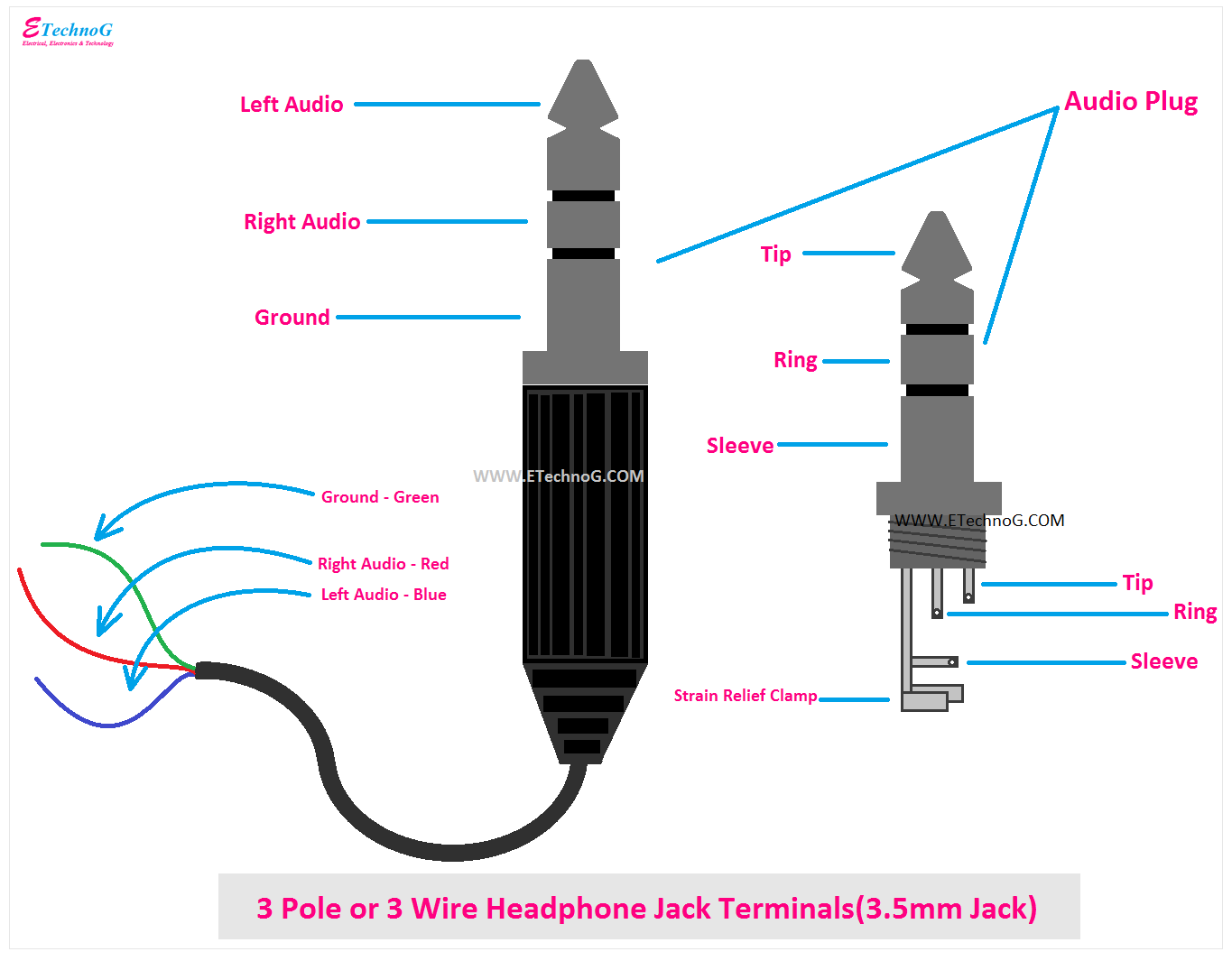
- Input Jack: Wiring diagrams depict the type of input jack used, such as 3.5mm TRS or XLR, and its connection to the internal circuitry.
- Amplification Stage: Some headphones incorporate an amplification stage to boost the signal level. Diagrams show the components and configuration of this stage.
- Crossover Network: If multiple drivers are used, a crossover network separates the incoming signal into different frequency ranges, directing each range to the appropriate driver.
- Driver Connection: Diagrams trace the signal path to each driver, revealing the type of connection (e.g., single-ended or balanced) and the polarity of the connections.
Understanding the signal path and its integrity is essential for troubleshooting and modifying headphones. By analyzing the wiring diagram, one can identify potential sources of signal loss, distortion, or interference. This knowledge empowers users to make informed decisions about component upgrades, cable selection, and other modifications to optimize the sound quality and performance of their headphones.
Driver Configuration
In the realm of headphone wiring diagrams, driver configuration holds significant importance as it unveils the arrangement and types of drivers employed within the headphones. This aspect provides crucial insights into the sound characteristics, performance capabilities, and design choices of the headphones.
- Single Driver: Headphones with a single driver utilize a single transducer to produce sound across the entire frequency range. This configuration offers simplicity, affordability, and a coherent sound signature.
- Dual Drivers: Dual-driver headphones feature two separate drivers, typically a dynamic driver for bass and a balanced armature driver for treble. This arrangement enhances frequency response and clarity, often resulting in a more balanced and detailed sound.
- Multiple Drivers: Headphones with multiple drivers, such as triple-driver or quad-driver models, incorporate specialized drivers for specific frequency ranges. This configuration allows for precise control over the sound signature, delivering exceptional accuracy and clarity across the entire spectrum.
- Hybrid Drivers: Hybrid driver headphones combine different types of drivers, such as dynamic and electrostatic drivers, to achieve a wider frequency range and improved sound quality. This configuration offers the advantages of multiple driver arrangements while maintaining a compact design.
Understanding driver configuration through headphone wiring diagrams empowers users to make informed decisions about the sound they desire. Whether seeking a balanced single-driver experience, the enhanced clarity of dual drivers, the precision of multiple drivers, or the versatility of hybrid drivers, wiring diagrams provide a roadmap to the inner workings of headphones, enabling users to select the perfect pair for their listening preferences.
Troubleshooting
Headphone wiring diagrams serve as invaluable tools for troubleshooting various issues that may arise in headphones. By offering a clear visual representation of the circuitry, these diagrams empower users to identify and resolve problems, ensuring optimal performance and sound quality.
- Component Identification: Wiring diagrams enable users to pinpoint the exact components that may be causing issues. By tracing the signal path and identifying the specific components involved, users can focus their troubleshooting efforts on the most likely culprits.
- Visual Inspection: Wiring diagrams provide a comprehensive visual inspection of the circuitry. This allows users to check for loose connections, broken wires, or damaged components. By identifying these issues early on, users can prevent further damage and ensure the longevity of their headphones.
- Signal Tracing: Wiring diagrams facilitate signal tracing, which involves following the signal path to identify points of signal loss or distortion. By analyzing the signal at various points in the circuitry, users can isolate the source of the problem and implement targeted solutions.
- Component Replacement: In cases where components fail or become damaged, wiring diagrams guide users through the process of replacing them. Diagrams provide clear instructions on how to remove and install new components, ensuring proper functionality and maintaining the integrity of the headphone circuitry.
Overall, the ability to troubleshoot headphone issues using wiring diagrams empowers users to maintain and repair their headphones, extending their lifespan and ensuring a consistently exceptional listening experience.
Modification
Modification: Diagrams are valuable for those seeking to modify their headphones, as they provide insights into the internal connections. Headphone wiring diagrams play a crucial role in facilitating headphone modifications by providing a visual representation of the internal circuitry, component interactions, and signal flow. These diagrams empower users to understand the inner workings of their headphones, identify areas for improvement, and implement modifications to enhance sound quality, functionality, or aesthetics.
Real-life examples of headphone modifications enabled by wiring diagrams include:
- Upgrading headphone drivers to improve sound quality and frequency response.
- Installing inline controls or microphones to enhance convenience and functionality.
- Replacing cables to reduce noise or improve durability.
- Customizing the headphone’s appearance with different earpads or headband covers.
The practical applications of understanding headphone wiring diagrams extend beyond simple modifications. These diagrams provide valuable insights for:
- Designing and building custom headphones from scratch.
- Repairing and troubleshooting headphone issues, reducing the need for professional assistance.
- Developing a deeper understanding of headphone technology and acoustics.
In summary, headphone wiring diagrams are indispensable tools for those seeking to modify their headphones. They provide a comprehensive understanding of the internal connections and signal flow, enabling users to make informed decisions about modifications, troubleshoot issues, and explore the intricacies of headphone design.
Historical Development
In the realm of “Headphone Wiring Diagram”, historical development plays a pivotal role, providing a tangible connection to the evolution of headphone technology and the accompanying changes in wiring designs. By examining the historical context, we gain insights into the technological advancements, design innovations, and cultural influences that have shaped the headphones we use today.
- Evolution of Driver Technology: Wiring diagrams reveal the progression of driver technology, from early single-driver designs to the sophisticated multi-driver configurations used in modern headphones. They showcase the shift from moving coil drivers to planar magnetic and electrostatic drivers, each with its unique advantages and sound characteristics.
- Materials and Manufacturing Techniques: Historical wiring diagrams provide insights into the evolution of materials and manufacturing techniques used in headphone construction. They illustrate the transition from bulky and heavy materials to lightweight and durable ones, as well as the adoption of advanced manufacturing processes that have improved sound quality and reliability.
- Connector Standards and Compatibility: Wiring diagrams document the development of connector standards and compatibility issues over time. They show the transition from proprietary connectors to standardized ones, such as the 3.5mm jack and various wireless protocols. This evolution has played a crucial role in ensuring compatibility between headphones and different audio sources.
- Cultural Influences and Design Aesthetics: Wiring diagrams reflect the cultural influences and design aesthetics that have shaped headphone development. They showcase how headphones have evolved from utilitarian devices to fashion accessories, with an emphasis on ergonomics, comfort, and visual appeal.
By delving into historical wiring diagrams, we gain a deeper appreciation for the technological advancements and design innovations that have brought us the high-fidelity audio experiences we enjoy today. These diagrams serve as a valuable resource for understanding the evolution of headphone technology and its impact on the way we listen to music and engage with the world around us.


Related Posts


