Leviton 3-Way Switch Wiring Schematic is a detailed diagram that illustrates the electrical connections and circuit layout for a Leviton 3-way switch, commonly used in home or building wiring to control lighting from multiple locations.
Leviton 3-Way Switch Wiring Schematics are crucial for ensuring proper electrical functionality and safety. They provide clear instructions for connecting the switch to electrical wires, grounding, and other electrical components. Adhering to the schematic ensures the correct operation of the switch and prevents potential electrical hazards.
A significant historical development in Leviton 3-Way Switch Wiring Schematics was the introduction of color-coded wires, which simplifies the identification of individual wires and their corresponding connections. This color-coding scheme has become widely adopted in the electrical industry.
Understanding the essential aspects of Leviton 3 Way Switch Wiring Schematics is crucial for electrical safety and proper functioning of lighting control systems. These aspects encompass various dimensions, including:
- Wiring Diagram: Visual representation of electrical connections.
- Circuit Layout: Arrangement of electrical components in the circuit.
- Switch Operation: Mechanism for controlling lighting from multiple locations.
- Electrical Connections: Proper connection of wires to the switch and other components.
- Color-Coding: Standardization of wire colors for easy identification.
- Grounding: Safe dissipation of electrical current to the ground.
- Safety Precautions: Guidelines for preventing electrical hazards.
- Troubleshooting: Identifying and resolving electrical issues.
- Compliance: Adherence to electrical codes and standards.
These aspects are interconnected and play vital roles in ensuring the reliable and safe operation of Leviton 3 Way Switch Wiring Schematics. For example, a clear wiring diagram simplifies the installation process, while proper grounding protects against electrical shocks. Adhering to safety precautions and following electrical codes guarantees compliance with industry standards and minimizes the risk of electrical fires.
Wiring Diagram
Within the context of “Leviton 3 Way Switch Wiring Schematic”, the “Wiring Diagram: Visual representation of electrical connections” serves as a crucial element in understanding and executing the proper electrical connections for a 3-way switch setup. It provides a clear and concise diagrammatic representation of the electrical components and their interconnections, guiding electricians and DIY enthusiasts through the installation process.
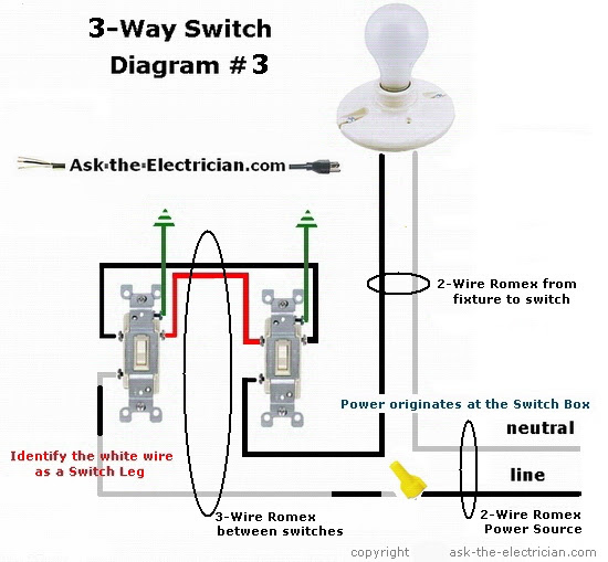
- Circuit Layout: The wiring diagram depicts the arrangement of electrical components within the circuit, including the 3-way switch, traveler wires, and power source. This layout ensures that the switch operates correctly and controls the lighting from multiple locations.
- Component Identification: The diagram clearly labels each electrical component, such as the switch, wires, and terminals. This identification aids in the accurate connection of wires to the appropriate terminals, preventing electrical hazards.
- Color-Coding: Modern wiring diagrams utilize color-coded wires to simplify the identification of individual wires and their corresponding connections. This color-coding scheme aligns with industry standards and enhances the ease of installation.
- Troubleshooting: In the event of electrical issues, the wiring diagram serves as a valuable troubleshooting tool. By referring to the diagram, electricians can quickly identify the potential source of the problem and implement appropriate solutions.
Overall, the “Wiring Diagram: Visual representation of electrical connections” plays a vital role in the successful installation and maintenance of Leviton 3 Way Switch Wiring Schematics. It provides a comprehensive visual guide, ensuring proper electrical connections, component identification, troubleshooting, and adherence to safety standards.
Circuit Layout
Within the context of a Leviton 3 Way Switch Wiring Schematic, the circuit layout plays a critical role in determining the proper arrangement and interconnection of electrical components to achieve the desired functionality. The circuit layout defines the overall structure of the electrical circuit, ensuring that the 3-way switch operates correctly and controls the lighting from multiple locations.
A well-designed circuit layout optimizes the flow of electricity, minimizes electrical resistance, and enhances the efficiency of the lighting system. It considers factors such as the placement of the 3-way switch, the routing of traveler wires, and the connection to the power source. By adhering to established electrical codes and best practices, the circuit layout ensures the safe and reliable operation of the wiring schematic.
Real-life examples of circuit layout in Leviton 3 Way Switch Wiring Schematics include:
- A single-pole, 3-way switch circuit, where one switch controls a single light fixture from two different locations.
- A multi-way switch circuit, where multiple 3-way switches are used to control a single light fixture from several locations.
- A complex lighting system, where multiple 3-way switches are combined with other electrical components, such as dimmers or motion sensors, to create a sophisticated lighting control system.
Understanding the circuit layout is essential for troubleshooting and maintenance purposes. By analyzing the circuit layout, electricians can quickly identify potential problems, such as loose connections, faulty switches, or damaged wires. This understanding also enables the modification or expansion of the wiring schematic to accommodate changes in the lighting system or the addition of new electrical components.
Switch Operation
Within the context of Leviton 3 Way Switch Wiring Schematics, switch operation holds critical importance as the mechanism that enables lighting control from multiple locations. This operation relies on the coordinated interaction of various components and electrical principles to achieve its functionality.
-
Three-Way Switch:
The heart of the system, a three-way switch is a specialized switch designed to control a single light fixture from two different locations. It features three terminals, with the common terminal connecting to the power source and the other two terminals connecting to the traveler wires.
-
Traveler Wires:
These wires serve as the communication channel between the two three-way switches. When one switch is toggled, it sends a signal through the traveler wires, causing the other switch to change state and toggle the light fixture.
-
Neutral Wire:
The neutral wire provides a complete circuit path for the electrical current to flow back to the power source. It is essential for the proper functioning of the three-way switch circuit.
-
Ground Wire:
The ground wire ensures electrical safety by providing a low-resistance path for any stray electrical currents to safely dissipate into the ground, minimizing the risk of electrical shocks or damage to equipment.
The interplay of these components enables the characteristic operation of Leviton 3 Way Switch Wiring Schematics, allowing for convenient and flexible lighting control from multiple locations. Understanding the nuances of switch operation is paramount for proper installation, troubleshooting, and maintenance of these wiring schematics.
Electrical Connections
In the context of “Leviton 3 Way Switch Wiring Schematic”, electrical connections play a pivotal role in ensuring the proper functionality and safety of the lighting control system. These connections involve the precise joining of wires to the terminals of the three-way switch, traveler wires, and other electrical components, such as the power source and ground wire.
The accuracy of these electrical connections is critical because any loose or incorrect connections can lead to electrical hazards, such as short circuits, overheating, or even electrical fires. A secure and proper connection ensures that the electrical current flows smoothly through the circuit, enabling the three-way switch to effectively control the lighting fixture from multiple locations.
Real-life examples of electrical connections within “Leviton 3 Way Switch Wiring Schematic” include:
- Connecting the common terminal of the three-way switch to the power source using a black or red wire.
- Connecting the traveler wires between the two three-way switches using white or colored wires.
- Connecting the neutral wire to the neutral terminal of the light fixture and the neutral bus bar in the electrical panel.
- Connecting the ground wire to the ground terminal of the light fixture and the grounding bus bar in the electrical panel.
Understanding the principles and practices of electrical connections is essential for the safe and effective installation and maintenance of “Leviton 3 Way Switch Wiring Schematic”. This understanding enables electricians and homeowners to troubleshoot and resolve any electrical issues that may arise, ensuring the continued reliable operation of their lighting control systems.
Color-Coding
Within the context of “Leviton 3 Way Switch Wiring Schematic”, color-coding plays a critical role in simplifying the identification of individual wires and their corresponding connections. This standardization ensures consistency in electrical wiring practices, enabling electricians and homeowners to quickly and accurately identify the purpose of each wire, reducing the risk of errors and ensuring the proper functioning of the lighting control system.
Color-coding is a crucial component of “Leviton 3 Way Switch Wiring Schematic” because it provides a visual cue for distinguishing between different types of wires. In a typical three-way switch circuit, the following color-coding scheme is commonly used:
- Black or red: Power source
- White or colored: Traveler wires
- Green or bare copper: Ground wire
By adhering to this color-coding scheme, electricians can easily identify which wires should be connected to the common terminal, traveler terminals, and ground terminal of the three-way switches, respectively.
Real-life examples of color-coding within “Leviton 3 Way Switch Wiring Schematic” include:
- Connecting the black wire from the power source to the common terminal of the three-way switch.
- Connecting the white traveler wire to one of the traveler terminals on the first three-way switch and to the corresponding traveler terminal on the second three-way switch.
- Connecting the green ground wire to the ground terminal on both three-way switches and to the grounding bus bar in the electrical panel.
Understanding the principles and practices of color-coding is essential for the safe and effective installation and maintenance of “Leviton 3 Way Switch Wiring Schematic”. This understanding enables electricians and homeowners to troubleshoot and resolve any electrical issues that may arise, ensuring the continued reliable operation of their lighting control systems.
Grounding
In the context of “Leviton 3 Way Switch Wiring Schematic”, grounding plays a crucial role in ensuring the safety and proper functioning of the lighting control system. Grounding involves connecting the electrical system to the ground, providing a low-resistance path for any stray electrical currents to safely dissipate into the earth, minimizing the risk of electrical shocks or damage to equipment.
Grounding is a critical component of “Leviton 3 Way Switch Wiring Schematic” because it helps to prevent electrical faults and ensures the safe operation of the lighting system. Without proper grounding, electrical currents can accumulate in the system, leading to electrical hazards such as short circuits, overheating, or even electrical fires.
Real-life examples of grounding within “Leviton 3 Way Switch Wiring Schematic” include:
- Connecting the ground wire from the electrical panel to the ground terminal on the three-way switches.
- Connecting the ground wire from the light fixture to the ground terminal on the three-way switches.
- Connecting the ground wire to the grounding bus bar in the electrical panel.
Understanding the principles and practices of grounding is essential for the safe and effective installation and maintenance of “Leviton 3 Way Switch Wiring Schematic”. This understanding enables electricians and homeowners to troubleshoot and resolve any electrical issues that may arise, ensuring the continued reliable operation of their lighting control systems.
Safety Precautions
Within the context of “Leviton 3 Way Switch Wiring Schematic”, safety precautions play a paramount role in ensuring the safe and reliable operation of the lighting control system. These precautions encompass a range of measures designed to prevent electrical hazards, protect against electrical shocks, and minimize the risk of electrical fires.
-
Proper Grounding:
Ensuring proper grounding provides a safe path for electrical current to dissipate into the earth, preventing electrical shocks and equipment damage.
-
Secure Electrical Connections:
Tightening electrical connections and using appropriate connectors prevents loose connections that can cause overheating, arcing, and potential fires.
-
Adequate Wire Sizing:
Selecting the correct wire gauge for the electrical load ensures that the wires can safely carry the electrical current without overheating.
-
Circuit Protection:
Using circuit breakers or fuses prevents electrical overloads that can lead to electrical fires or equipment damage.
Adhering to these safety precautions is crucial for the safe and effective installation and maintenance of “Leviton 3 Way Switch Wiring Schematic”. By following established electrical codes and best practices, electricians and homeowners can minimize electrical hazards and ensure the continued reliable operation of their lighting control systems.
Troubleshooting
Within the context of “Leviton 3 Way Switch Wiring Schematic”, troubleshooting plays a pivotal role in maintaining the safe and reliable operation of the lighting control system. Troubleshooting encompasses a systematic approach to identifying and resolving electrical issues, ensuring that the wiring schematic functions as intended and potential hazards are mitigated.
Troubleshooting is a critical component of “Leviton 3 Way Switch Wiring Schematic” because it enables electricians and homeowners to diagnose and rectify electrical problems that may arise during installation, maintenance, or regular use. Without proper troubleshooting, electrical issues can remain undetected, potentially leading to safety hazards, equipment damage, or disruption of lighting control.
Real-life examples of troubleshooting within “Leviton 3 Way Switch Wiring Schematic” include:
- Identifying a loose connection that causes flickering lights or intermittent switch operation.
- Diagnosing a faulty switch that prevents the light fixture from turning on or off.
- Tracing a short circuit that triggers circuit breakers or fuses to trip.
Understanding the principles and practices of troubleshooting is essential for the effective maintenance and repair of “Leviton 3 Way Switch Wiring Schematic”. This understanding enables electricians and homeowners to identify and resolve electrical issues promptly, ensuring the continued reliable operation of their lighting control systems.
Compliance
Within the context of “Leviton 3 Way Switch Wiring Schematic”, compliance with electrical codes and standards holds paramount importance in ensuring the safety, reliability, and efficiency of the lighting control system. Electrical codes and standards are established guidelines based on extensive research and practical experience, providing a framework for safe electrical practices and installations.
Adherence to these codes and standards is a critical component of “Leviton 3 Way Switch Wiring Schematic” as it directly impacts the safety and proper functioning of the electrical system. By following established guidelines, electricians and homeowners can minimize the risk of electrical hazards, prevent equipment damage, and ensure the longevity of the lighting control system.
Real-life examples of compliance within “Leviton 3 Way Switch Wiring Schematic” include:
- Using appropriate wire sizes as per electrical code requirements to ensure safe current-carrying capacity.
- Installing ground fault circuit interrupters (GFCIs) in areas with potential moisture exposure to prevent electrical shocks.
- Adhering to the National Electrical Code (NEC) guidelines for switch box sizing and placement to maintain proper spacing and accessibility.
Understanding the practical applications of compliance with electrical codes and standards in “Leviton 3 Way Switch Wiring Schematic” is essential for the safe and effective installation and maintenance of the lighting control system. This understanding enables electricians and homeowners to mitigate electrical hazards, ensure code compliance, and contribute to the overall safety and reliability of their electrical systems.


Related Posts


