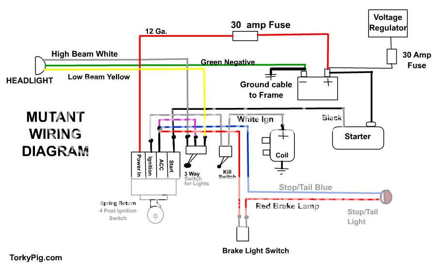
A Spireon Gps Wiring Diagram provides a visual representation of the electrical connections necessary to install a Spireon GPS tracking device. The diagram specifies the location of the device’s wires, their function, and the corresponding connections to the vehicle’s wiring system.
This wiring diagram is crucial for ensuring proper device operation, as it allows for the correct transfer of power, data, and communication signals. Incorrect wiring can not only compromise the GPS device’s functionality but also potentially damage the vehicle’s electrical systems.
Throughout automotive history, the introduction of GPS tracking systems has revolutionized fleet management and security. Spireon’s wiring diagrams have played a central role in this evolution, enabling the effective integration of GPS technology into vehicles. With its comprehensive instructions and clear visuals, the Spireon Wiring Diagram empowers users to seamlessly connect their GPS tracking devices, unlocking the full range of benefits that this technology offers.
The term “Spireon Gps Wiring Diagram” encompasses several key aspects that are crucial for understanding its role and significance. These aspects, explored through the lens of the noun phrase, provide a comprehensive overview of the topic.
- Device Compatibility: The wiring diagram specifies the compatibility of the GPS tracking device with specific vehicle makes and models.
- Electrical Connections: It outlines the precise electrical connections required between the GPS device and the vehicle’s wiring harness.
- Power Supply: The diagram indicates the power source and the method of connecting the GPS device to the vehicle’s electrical system.
- Data Transfer: It details the data transfer protocols and the wiring connections for transmitting data between the GPS device and the monitoring platform.
- Antenna Placement: The wiring diagram provides guidance on the optimal placement of the GPS antenna for maximum signal reception.
- Security Features: It may include instructions for implementing security measures, such as tamper detection and ignition cut-off.
- Customization Options: The diagram can indicate any customization options available for tailoring the wiring configuration to specific vehicle requirements.
- Troubleshooting Guide: It often includes troubleshooting tips and diagnostic steps to assist with resolving any installation or operational issues.
- Compliance Standards: The wiring diagram may adhere to industry standards and regulations, ensuring compliance with safety and quality guidelines.
- Technical Support: It can provide contact information for technical support, allowing users to access assistance if needed.
These aspects collectively contribute to the effective installation and operation of Spireon GPS tracking devices. Understanding these aspects is essential for system integrators, fleet managers, and anyone involved in the deployment and maintenance of GPS tracking solutions.
Device Compatibility
Device compatibility is a critical component of the Spireon GPS Wiring Diagram. The diagram outlines the specific vehicle makes and models that are compatible with the GPS tracking device, ensuring that the device can be properly installed and function effectively within the vehicle’s electrical system.
For example, a Spireon GPS Wiring Diagram for the Ford F-150 will provide detailed instructions on how to connect the device to the vehicle’s wiring harness, taking into account the specific electrical configurations and CAN bus protocols used in that particular vehicle model. This ensures that the GPS device can communicate seamlessly with the vehicle’s systems, providing accurate location data and enabling remote monitoring and control.
Understanding the device compatibility aspect of the Spireon GPS Wiring Diagram is essential for system integrators and fleet managers. By carefully matching the GPS tracking device with the appropriate vehicle, they can avoid compatibility issues, ensure reliable operation, and maximize the benefits of the GPS tracking solution.
Electrical Connections
The “Electrical Connections” component of the Spireon GPS Wiring Diagram plays a critical role in ensuring the proper functioning and reliability of the GPS tracking system. It provides a detailed roadmap for connecting the GPS device to the vehicle’s electrical system, taking into account the specific voltage requirements, power consumption, and data transfer protocols.
For instance, the wiring diagram may specify the connection of the GPS device to the vehicle’s ignition system, allowing the device to power on and off automatically with the vehicle. It may also outline the connection to the vehicle’s CAN bus, enabling the GPS device to communicate with other vehicle systems, such as the engine control unit or tire pressure monitoring system.
Understanding the electrical connections is essential for system integrators and fleet managers to ensure that the GPS tracking device is properly installed and integrated with the vehicle’s systems. By following the wiring diagram precisely, they can avoid electrical faults, ensure data integrity, and maximize the effectiveness of the GPS tracking solution.
In summary, the “Electrical Connections” component of the Spireon GPS Wiring Diagram is a critical element for the successful deployment and operation of GPS tracking devices in vehicles. It provides clear instructions for connecting the device to the vehicle’s electrical system, ensuring reliable power supply, data communication, and integration with other vehicle systems.
Power Supply
“Power Supply” is a fundamental aspect of the Spireon GPS Wiring Diagram, providing critical instructions on how to connect the GPS device to the vehicle’s electrical system and ensure a reliable power source for its operation. Understanding and following these instructions are essential for a successful and efficient GPS tracking system installation.
- Battery Connection: The wiring diagram specifies the type of battery to be used and how to connect it to the GPS device. This includes the battery’s voltage, capacity, and the correct polarity of the connections.
- Power Harness: The diagram provides details about the power harness that connects the GPS device to the vehicle’s electrical system. It includes information on the harness’s pinout, wire colors, and the location of the connection point.
- Power Management: The wiring diagram may also include instructions on how to manage the GPS device’s power consumption. This can involve setting up power-saving modes or connecting the device to an ignition-controlled power source.
- Fuses and Circuit Protection: The diagram specifies the appropriate fuses and circuit protection measures to protect the GPS device and the vehicle’s electrical system from electrical faults or overloads.
Properly addressing the “Power Supply” aspect of the Spireon GPS Wiring Diagram ensures that the GPS device receives a stable and reliable power supply, enabling continuous operation, accurate tracking, and effective data transmission. Neglecting these instructions can lead to power issues, device malfunctions, or even electrical hazards.
Data Transfer
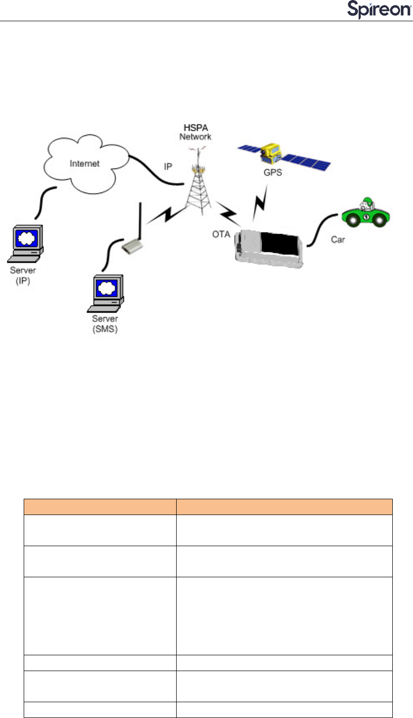
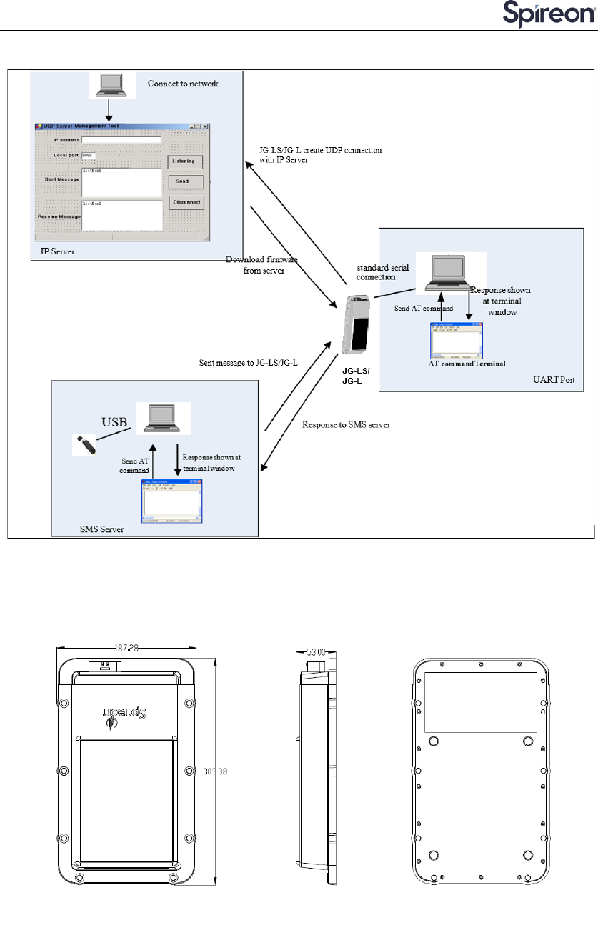
Within the context of the Spireon GPS Wiring Diagram, the “Data Transfer” component plays a critical role in establishing a reliable and efficient communication channel between the GPS device installed in the vehicle and the monitoring platform. This data transfer capability is essential for transmitting vital information, such as the vehicle’s location, speed, and other operational data, to the monitoring platform for analysis, visualization, and decision-making.
The wiring diagram provides detailed instructions on the wiring connections required for data transfer, including the type of data cable to be used, the pinouts, and the connection points on both the GPS device and the vehicle’s wiring harness. It also specifies the data transfer protocols supported by the GPS device, such as NMEA 2000 or J1939, and the configuration settings necessary to ensure compatibility with the monitoring platform.
Understanding and correctly implementing the “Data Transfer” component of the Spireon GPS Wiring Diagram is crucial for ensuring the smooth flow of data from the GPS device to the monitoring platform. This data transfer capability enables fleet managers, logistics companies, and other users to monitor vehicle activity in real-time, track vehicle location history, analyze driving behavior, and make informed decisions to optimize operations, improve safety, and enhance overall fleet efficiency.
Antenna Placement
Within the comprehensive framework of the Spireon GPS Wiring Diagram, the aspect of “Antenna Placement” holds significant importance in ensuring reliable and accurate GPS tracking performance. The wiring diagram provides meticulous instructions on the optimal positioning of the GPS antenna to maximize signal reception, a critical factor in maintaining uninterrupted communication between the GPS device and the monitoring platform.
- Antenna Type and Compatibility: The wiring diagram specifies the type of GPS antenna compatible with the device and provides guidance on selecting an antenna with the appropriate gain and frequency range for the intended application.
- Mounting Location: The diagram illustrates the ideal mounting location for the GPS antenna, considering factors such as visibility to the sky, avoidance of metallic obstructions, and proximity to potential sources of interference.
- Antenna Orientation: The wiring diagram provides instructions on the correct orientation of the GPS antenna, ensuring that it is positioned perpendicular to the ground and aligned with the horizon to maximize signal reception.
- Cable Length and Routing: The diagram specifies the appropriate length and routing of the antenna cable, taking into account signal loss and potential interference from other electrical components in the vehicle.
By carefully following the “Antenna Placement” guidelines outlined in the Spireon GPS Wiring Diagram, system integrators and fleet managers can ensure that the GPS antenna is optimally positioned for maximum signal reception. This, in turn, contributes to accurate and reliable GPS tracking data, enabling effective fleet monitoring, vehicle tracking, and a wide range of other applications that rely on precise location information.
Security Features
Within the context of the Spireon GPS Wiring Diagram, the inclusion of security features plays a vital role in safeguarding the GPS tracking system and the vehicle it is installed in. These security measures are designed to deter theft, unauthorized access, and tampering, ensuring the integrity and reliability of the tracking data.
Cause and Effect
The Spireon GPS Wiring Diagram provides detailed instructions on how to implement security features such as tamper detection and ignition cut-off. These features are crucial components of the overall GPS tracking system, as they:
- Prevent Theft: Tamper detection mechanisms, such as motion sensors or door/hood switches, can trigger alerts if the vehicle is moved or accessed without authorization, deterring theft attempts.
- Immobilize the Vehicle: Ignition cut-off features allow fleet managers to remotely disable the vehicle’s ignition, preventing unauthorized use or recovery in the event of theft.
By incorporating these security features into the wiring diagram, Spireon empowers users to enhance the security of their vehicles and valuable assets, mitigating risks and providing peace of mind.
Real-Life Examples
Practical applications of security features in Spireon GPS Wiring Diagrams can be seen in various industries:
- Fleet Management: Transportation and logistics companies use tamper detection and ignition cut-off features to protect their vehicles from theft and unauthorized usage.
- Construction: Construction equipment fitted with GPS tracking devices can be secured using tamper detection to prevent unauthorized operation or theft of expensive machinery.
- Personal Vehicles: Individuals can install GPS tracking devices with security features to safeguard their vehicles from theft and provide real-time tracking in case of emergencies.
These examples demonstrate the practical value of security features in Spireon GPS Wiring Diagrams, contributing to the overall effectiveness and reliability of GPS tracking solutions.
Summary
In summary, the “Security Features” component of the Spireon GPS Wiring Diagram is a critical aspect that addresses the need for theft prevention and unauthorized access control in GPS tracking systems. By providing clear instructions on implementing tamper detection and ignition cut-off mechanisms, Spireon empowers users to enhance the security of their vehicles and assets, ensuring the integrity of tracking data and providing peace of mind.
Customization Options
Within the comprehensive framework of the Spireon GPS Wiring Diagram, the provision of customization options empowers users to tailor the wiring configuration to meet specific vehicle requirements, enhancing the versatility and adaptability of the GPS tracking solution.
Real-Life Examples
- Vehicle-Specific Wiring Harnesses: Spireon offers vehicle-specific wiring harnesses that are designed to plug directly into the vehicle’s electrical system, eliminating the need for extensive wire splicing or modifications.
- Configurable Input/Output Ports: Some Spireon GPS devices feature configurable input/output ports that can be programmed to interface with various sensors, accessories, or external devices, allowing for the integration of additional functionality.
- Customizable Data Reporting: The wiring diagram may include instructions on how to customize the frequency and format of data reporting to suit the specific needs of the user, optimizing data usage and minimizing unnecessary data transmission.
Practical Applications
The customization options available in the Spireon GPS Wiring Diagram enable users to adapt the GPS tracking solution to a wide range of applications, including:
- Fleet Telematics: Customization options allow fleet managers to tailor the wiring configuration to meet the specific requirements of their vehicles, whether they are cars, trucks, or specialized equipment.
- Asset Tracking: The ability to customize the wiring harness and data reporting makes Spireon GPS devices suitable for tracking a variety of assets, such as trailers, containers, or machinery.
- Personal Vehicle Monitoring: Individuals can customize the wiring configuration to integrate GPS tracking into their personal vehicles, enabling features such as real-time tracking, geofencing, and vehicle diagnostics.
In summary, the “Customization Options” component of the Spireon GPS Wiring Diagram plays a vital role in extending the capabilities and adaptability of the GPS tracking solution. By providing users with the ability to tailor the wiring configuration and functionality to their specific requirements, Spireon empowers them to implement GPS tracking solutions that seamlessly integrate with their vehicles and applications.
Troubleshooting Guide
Within the context of the Spireon GPS Wiring Diagram, the inclusion of a troubleshooting guide serves as a valuable resource for system integrators, fleet managers, and anyone involved in the installation and maintenance of GPS tracking devices. This guide provides a comprehensive set of troubleshooting tips and diagnostic steps to assist with resolving any installation or operational issues that may arise.
The troubleshooting guide is a critical component of the Spireon GPS Wiring Diagram because it empowers users to identify and resolve common problems without the need for extensive technical expertise. By following the step-by-step instructions and diagnostic procedures outlined in the guide, users can quickly pinpoint the source of the issue and implement effective solutions.
For example, the troubleshooting guide may include instructions on how to diagnose and resolve issues such as:
- GPS signal loss
- Power supply problems
- Data transmission errors
- Software configuration issues
By providing clear and concise troubleshooting guidance, Spireon empowers users to minimize downtime, optimize system performance, and ensure the reliable operation of their GPS tracking solutions.
In summary, the troubleshooting guide included in the Spireon GPS Wiring Diagram is an essential resource that enables users to troubleshoot and resolve installation or operational issues efficiently. This guide contributes to the overall effectiveness and reliability of the GPS tracking solution, empowering users to maintain optimal system performance and maximize the benefits of GPS technology.
Compliance Standards
The “Compliance Standards” aspect of the Spireon GPS Wiring Diagram plays a critical role in ensuring the safety and reliability of the GPS tracking solution. By adhering to industry standards and regulations, Spireon ensures that its wiring diagrams meet the highest standards of quality and safety, mitigating potential risks and liabilities.
One key industry standard that Spireon GPS Wiring Diagrams often adhere to is the SAE J1455 standard, which defines the electrical and physical requirements for heavy-duty vehicle electrical systems. By complying with this standard, Spireon wiring diagrams provide clear and consistent instructions for the installation of GPS tracking devices in heavy-duty vehicles, ensuring compatibility and proper functioning.
Another important aspect of compliance is meeting safety regulations. The misuse of GPS tracking devices can pose safety risks, such as distraction while driving or invasion of privacy. By adhering to regulations, such as the Federal Motor Carrier Safety Administration (FMCSA) regulations in the United States, Spireon GPS Wiring Diagrams help ensure that GPS tracking devices are installed and used in a responsible and compliant manner.
In summary, the “Compliance Standards” component of the Spireon GPS Wiring Diagram is a critical aspect that ensures the safety, reliability, and regulatory compliance of GPS tracking solutions. By adhering to industry standards and regulations, Spireon empowers users to install and operate their GPS tracking systems with confidence, knowing that they meet the highest standards of quality and safety.
Technical Support
Within the comprehensive framework of the Spireon GPS Wiring Diagram, the provision of technical support plays a vital role in ensuring the successful installation, operation, and maintenance of GPS tracking devices. By providing contact information for technical support, Spireon empowers users to access expert assistance whenever they encounter challenges or require guidance.
- Dedicated Support Channels: Spireon offers dedicated support channels, such as phone lines, email, and online chat, allowing users to connect with technical support representatives directly. This ensures prompt and personalized assistance, minimizing downtime and maximizing system uptime.
- Remote Troubleshooting: Through remote troubleshooting capabilities, Spireon’s technical support team can remotely access the GPS device and wiring configuration to identify and resolve issues. This eliminates the need for on-site visits, reducing service costs and expediting the resolution process.
- Documentation and Knowledge Base: In addition to direct support, Spireon provides comprehensive documentation and a knowledge base accessible to users. These resources offer self-help guides, FAQs, and troubleshooting tips, empowering users to resolve common issues independently.
- Training and Certification: Spireon offers training programs and certification courses for system integrators and fleet managers. These programs provide in-depth knowledge of Spireon GPS devices and wiring diagrams, enabling users to confidently install, configure, and maintain their GPS tracking solutions.
By incorporating “Technical Support: It can provide contact information for technical support, allowing users to access assistance if needed.” into its wiring diagrams, Spireon ensures that users have access to the resources and support they need to successfully deploy and manage their GPS tracking solutions. This comprehensive approach enhances the overall user experience, maximizes the value of the GPS tracking investment, and contributes to the long-term success of GPS tracking initiatives.


Related Posts


