Wiring a lighted rocker switch involves connecting electrical wires to the switch terminals to control the flow of electricity to a light fixture. For example, in a bathroom, a lighted rocker switch may be used to turn on and off the vanity light, with the illuminated switch providing a locator light in the dark.
This technique is essential for providing convenient and safe lighting control in various settings. Its benefits include ease of use, durability, and the ability to locate the switch in low-light conditions. A key historical development in switch technology was the invention of the illuminated rocker switch in the 1950s, which greatly enhanced user convenience and safety.
In this article, we will delve deeper into the wiring process of a lighted rocker switch, exploring its components, circuit configurations, and practical applications to ensure efficient and reliable lighting control.
Wiring a lighted rocker switch involves several essential aspects that determine its functionality, safety, and user experience. Understanding these aspects is crucial for proper installation, maintenance, and troubleshooting.
- Circuit Configuration: Single-pole, double-pole, or three-way
- Voltage and Amperage: Compatibility with electrical system
- Wire Gauge: Thickness of wires used for connection
- Terminal Connections: Correct wire placement on switch terminals
- Grounding: Ensuring electrical safety
- Switch Location: Accessibility and convenience
- Illumination Type: LED, incandescent, or neon
- Faceplate: Style and material
These aspects are interconnected and influence the overall performance of the lighted rocker switch. For instance, the circuit configuration determines the number of circuits controlled by the switch, while the voltage and amperage ratings ensure compatibility with the electrical system. Proper terminal connections and grounding are essential for safety, while switch location and illumination type impact user experience. Understanding these aspects enables informed decision-making during switch selection, installation, and maintenance, ensuring reliable and efficient lighting control.
Circuit Configuration
In the context of wiring a lighted rocker switch, circuit configuration plays a significant role in determining the functionality and control of lighting circuits. It refers to the arrangement of switches and electrical connections that govern the flow of electricity to light fixtures.
-
Single-pole:
Single-pole switches are the most basic type, controlling a single circuit with one switch. They are commonly used for simple on/off control of a single light fixture, such as a lamp or ceiling light.
-
Double-pole:
Double-pole switches are used to control two circuits simultaneously, often employed in situations where separate control of two light fixtures is desired. For example, a double-pole switch can be used to control the lights on opposite sides of a room.
-
Three-way:
Three-way switches are used in conjunction with each other to control a single circuit from multiple locations. This configuration is commonly found in hallways, stairwells, and other areas where convenient switching from different points is necessary.
-
Four-way:
Four-way switches are used in conjunction with three-way switches to control a single circuit from multiple locations, providing additional flexibility in lighting control. They are often employed in larger spaces or complex lighting setups.
Understanding circuit configuration is essential when wiring a lighted rocker switch, as it determines the number of switches required, the type of switch used, and the wiring connections necessary to achieve the desired lighting control. Proper circuit configuration ensures efficient and safe operation of lighting systems.
Voltage and Amperage
When wiring a lighted rocker switch, the voltage and amperage compatibility of the switch with the electrical system is of utmost importance. The voltage refers to the electrical potential difference between two points in the circuit, while the amperage represents the flow of electrical current. It is essential to ensure that the switch is rated to handle the voltage and amperage of the electrical system in which it will be installed.
-
Voltage rating:
The voltage rating of the switch should match the voltage of the electrical system. Using a switch with a lower voltage rating can lead to overheating and potential failure, while using a switch with a higher voltage rating may not provide adequate protection and could pose safety hazards. -
Amperage rating:
The amperage rating of the switch should be equal to or greater than the maximum current that will flow through the switch. Using a switch with a lower amperage rating can cause the switch to trip or overheat, interrupting the flow of electricity and potentially damaging the switch or other components in the circuit. -
Load type:
The type of load connected to the switch, such as incandescent bulbs, LED lights, or motors, can affect the voltage and amperage requirements. It is important to consider the characteristics of the load when selecting a switch to ensure compatibility and proper operation. -
Circuit protection:
The electrical system should have appropriate circuit protection devices, such as fuses or circuit breakers, to safeguard the switch and other components from electrical overloads or short circuits. The voltage and amperage ratings of these protective devices should be coordinated with the switch ratings to provide a comprehensive protection strategy.
Understanding the voltage and amperage compatibility of a lighted rocker switch is crucial to ensure its safe and effective operation within an electrical system. Proper selection and installation of a compatible switch help prevent electrical hazards, ensure reliable circuit control, and extend the lifespan of the switch and other electrical components.
Wire Gauge
In the context of Wiring A Lighted Rocker Switch, wire gauge plays a pivotal role in ensuring the safe and efficient transmission of electrical current. Wire gauge refers to the thickness or cross-sectional area of the wire, which directly affects its current-carrying capacity and resistance to electrical flow.
When selecting the appropriate wire gauge for a lighted rocker switch, it is crucial to consider the amperage rating of the switch and the length of the wire run. A thicker wire gauge (lower number) indicates a larger cross-sectional area, allowing for a higher current flow with reduced resistance. Conversely, a thinner wire gauge (higher number) has a smaller cross-sectional area, limiting its current-carrying capacity and increasing resistance.
Using an undersized wire gauge for a lighted rocker switch can lead to several adverse effects. Excessive current flowing through a thin wire can cause overheating, insulation damage, and potential fire hazards. Additionally, increased resistance in the wire can lead to voltage drop, resulting in reduced light output or switch malfunction.
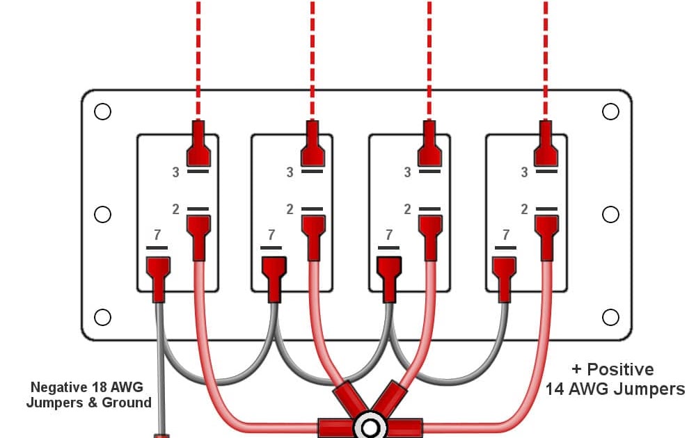
To ensure proper functionality and safety, it is essential to use the recommended wire gauge specified by the switch manufacturer. This ensures that the wire is capable of handling the current draw of the switch and the connected lighting fixture. Common wire gauges used for residential lighting applications range from 14 gauge to 18 gauge, with 14 gauge being suitable for higher current applications and longer wire runs.
Understanding the relationship between wire gauge and Wiring A Lighted Rocker Switch empowers individuals to make informed decisions when selecting and installing electrical wiring. Proper wire gauge selection contributes to the safe and efficient operation of lighting systems, preventing potential electrical hazards and ensuring optimal performance.
Terminal Connections
In the intricate process of Wiring A Lighted Rocker Switch, Terminal Connections, referring to the precise placement of wires on the switch terminals, hold paramount importance. Ensuring correct wire placement is not merely a matter of functionality but also of safety and longevity for the electrical system.
-
Terminal Identification:
Lighted rocker switches typically have three terminals: Line (L), Load (L1), and Ground (G). Identifying and differentiating these terminals is crucial for proper wiring, as incorrect connections can lead to malfunctions or safety hazards.
-
Wire Stripping and Insertion:
Before inserting wires into the terminals, it is essential to strip the insulation off the wire ends, exposing the bare copper conductors. The stripped length should be sufficient to securely wrap around the terminal screws, ensuring a tight and reliable connection.
-
Terminal Tightening:
Using a screwdriver, the terminal screws should be tightened firmly to secure the wires in place. Loose connections can result in arcing, overheating, and potential fire hazards. Overtightening, on the other hand, can damage the terminal screws or wires.
-
Grounding:
The Ground terminal, typically identified by a green screw, must be connected to the ground wire. Proper grounding provides a safe path for fault currents, protecting against electrical shocks and equipment damage.
Correct Terminal Connections in Wiring A Lighted Rocker Switch ensure a secure and efficient electrical connection. It prevents loose wires, arcing, and overheating, enhancing the safety and reliability of the lighting system. Moreover, proper wiring techniques contribute to the longevity of the switch and connected components, minimizing the risk of premature failures or costly repairs.
Grounding
In the context of Wiring A Lighted Rocker Switch, grounding plays a critical role in ensuring electrical safety by providing a low-resistance path for fault currents to flow safely to the ground, thereby preventing electrical shocks, equipment damage, and fire hazards.
-
Electrical Safety:
Proper grounding creates a safe electrical system by providing an alternative path for electricity to flow in the event of a fault, such as a short circuit. This prevents the buildup of dangerous voltages on the switch or other components, reducing the risk of electrical shocks.
-
Equipment Protection:
Grounding helps protect electrical equipment, including the lighted rocker switch, from damage. When a fault occurs, the excess current is safely diverted through the ground wire, preventing it from flowing through the switch and potentially causing overheating or burnout.
-
Compliance with Codes:
Grounding is a fundamental requirement in electrical codes and standards. Ensuring proper grounding not only enhances safety but also fulfills legal obligations and ensures compliance with building and electrical regulations.
-
Grounding Methods:
In Wiring A Lighted Rocker Switch, grounding is typically achieved by connecting the ground wire, usually bare or green-insulated, to the ground terminal on the switch. This terminal is then connected to the electrical panel’s grounding system, which is connected to the earth ground.
Understanding and implementing proper grounding techniques when Wiring A Lighted Rocker Switch is paramount for creating a safe and reliable electrical environment. By providing a safe path for fault currents, grounding safeguards both individuals and electrical equipment, minimizing the risk of electrical hazards and ensuring the longevity of the lighting system.
Switch Location
In the context of Wiring A Lighted Rocker Switch, switch location plays a crucial role in ensuring accessibility, convenience, and user experience. The placement of the switch directly impacts its ease of use, safety, and overall functionality within the electrical system.
Accessibility refers to the ability to easily reach and operate the switch. Ideally, the switch should be positioned at a comfortable height and within arm’s reach of the user. This is particularly important in areas where frequent switching is required, such as hallways, entryways, or near beds. Convenient switch placement enhances user experience and reduces the likelihood of accidents or discomfort.
Convenience also encompasses the visibility of the switch, especially in dimly lit or dark environments. A well-positioned switch should be readily visible, allowing users to locate and operate it effortlessly. This is where lighted rocker switches offer a significant advantage. The illuminated feature provides a visual cue, making the switch easy to find and use, even in low-light conditions. This enhanced visibility contributes to safety and convenience, particularly for individuals with impaired vision or in emergency situations.
In practical applications, switch location is often determined by building codes, architectural design, and user preferences. For instance, in residential settings, switches are typically installed adjacent to doorways or at the entrance of rooms, ensuring easy accessibility. In commercial or public spaces, switches may be placed at strategic locations to optimize traffic flow and user convenience. Understanding the relationship between switch location and accessibility is essential for creating user-friendly and efficient electrical systems.
Illumination Type
In the context of “Wiring A Lighted Rocker Switch,” the choice of illumination type LED, incandescent, or neon holds significant implications for both the wiring process and the overall functionality of the switch. Each illumination type possesses unique characteristics that influence the electrical requirements, installation considerations, and user experience.
Firstly, the voltage and amperage requirements vary depending on the illumination type. Incandescent bulbs typically operate at higher voltages and consume more amperage compared to LED or neon lights. This necessitates careful selection of the switch’s voltage and amperage ratings to ensure compatibility with the chosen illumination type. Mismatched ratings can lead to switch failure or potential safety hazards.
Secondly, the wiring configuration may differ based on the illumination type. LED lights often require a resistor to limit the current flow, which may necessitate additional wiring connections. Neon lights, on the other hand, require a starter or ballast to initiate and maintain their illumination, further influencing the wiring scheme. Understanding these illumination-specific wiring requirements is crucial for proper switch installation and functionality.
Furthermore, the illumination type impacts the user experience and aesthetic appeal of the switch. Incandescent bulbs emit a warm, yellowish light, providing a traditional ambiance. LED lights offer energy efficiency, longer lifespan, and a wide range of color options, allowing for customization and ambiance control. Neon lights produce a distinctive colored glow, often used for decorative or accent lighting. The choice of illumination type ultimately depends on the desired lighting effect, energy consumption considerations, and personal preferences.
Faceplate
In the context of “Wiring A Lighted Rocker Switch,” the faceplate serves as the visible and interactive component that houses the switch and provides an aesthetic touch to the electrical system. Its style and material play a significant role in enhancing the overall functionality, safety, and visual appeal of the switch installation.
-
Design and Aesthetics:
The faceplate’s design and aesthetics complement the interior dcor and personal preferences. Various shapes, colors, and finishes are available, ranging from classic to contemporary styles, allowing for seamless integration into different environments. -
Material and Durability:
The material of the faceplate influences its durability and resistance to wear and tear. Common materials include plastic, metal, and wood, each offering unique properties. Plastic faceplates are cost-effective and lightweight, while metal faceplates provide a sturdy and resilient option. Wooden faceplates add a natural and elegant touch. -
Size and Configuration:
The size and configuration of the faceplate should accommodate the switch and align with the electrical box. Standard faceplates come in single-gang or multi-gang configurations, catering to different switch arrangements. Oversized faceplates can provide additional coverage for uneven walls or imperfections. -
Safety Features:
Some faceplates incorporate safety features such as tamper-resistant construction or moisture resistance. Tamper-resistant faceplates prevent accidental access to live electrical components, enhancing safety in homes with children or curious individuals. Moisture-resistant faceplates are suitable for outdoor or humid environments, protecting the switch from water damage.
By considering the style, material, size, and safety features of the faceplate, individuals can make informed decisions that align with their functional requirements, aesthetic preferences, and safety concerns, ensuring a seamless and aesthetically pleasing integration of the lighted rocker switch into their electrical system.


Related Posts


