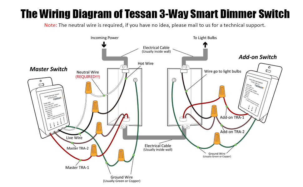
A Wiring A Dimmer Switch Diagram illustrates the electrical connections and components used to control the light intensity of a lighting fixture, typically using a potentiometer or other variable resistor. For instance, a three-way dimmer switch wiring diagram would show the connections between the switch, the light fixture, and the power source.
Dimmer switch diagrams are essential for electrical professionals and DIY enthusiasts, ensuring safe and effective lighting control. They offer benefits like energy efficiency by optimizing light output, creating ambiance and mood with adjustable brightness levels, and extending lamp life by reducing voltage and heat.
A key historical development was the introduction of solid-state dimmers in the 1960s, replacing mechanical dimmer switches and providing more precise and efficient light control.
This article further delves into the specific components, wiring configurations, and safety considerations associated with Wiring A Dimmer Switch Diagram, providing detailed guidance for electrical professionals and DIY enthusiasts.
Wiring A Dimmer Switch Diagram is a noun phrase that represents the technical instructions for connecting and configuring a dimmer switch to control the intensity of lighting fixtures. Understanding the key aspects of Wiring A Dimmer Switch Diagram is essential for electrical professionals and DIY enthusiasts to ensure safe and effective lighting control.
- Electrical Safety: Adhering to electrical codes and best practices to prevent electrical hazards.
- Circuit Compatibility: Matching the dimmer switch to the type of lighting circuit and load.
- Wiring Configuration: Identifying the correct wiring connections for the specific dimmer switch and lighting fixture.
- Load Rating: Ensuring the dimmer switch can handle the electrical load of the connected lighting fixture.
- Dimmer Type: Selecting the appropriate dimmer switch type based on the lighting technology (e.g., incandescent, LED).
- Control Interface: Understanding the different control interfaces available for dimmer switches (e.g., rotary knob, touch panel).
- Dimming Range: Determining the minimum and maximum light output levels achievable with the dimmer switch.
- Power Handling: Managing the electrical power flow through the dimmer switch and to the lighting fixture.
- Troubleshooting: Identifying and resolving common issues that may arise during the installation or operation of the dimmer switch.
- Compliance: Meeting regulatory requirements and industry standards related to dimmer switch installation and use.
These key aspects provide a comprehensive understanding of Wiring A Dimmer Switch Diagram, enabling individuals to safely and effectively control lighting intensity. Proper wiring ensures electrical safety, compatibility with different lighting systems, and optimal performance of the dimmer switch. Moreover, understanding these aspects allows for informed decision-making when selecting and installing dimmer switches, ultimately enhancing the functionality and aesthetics of lighting systems.
Electrical Safety
When dealing with “Wiring A Dimmer Switch Diagram,” electrical safety should be of utmost concern to prevent electrical hazards. Adhering to electrical codes and best practices ensures the safe installation and operation of dimmer switches, protecting users from potential risks.
- Proper Wiring: Ensure all electrical connections are secure and made in accordance with electrical codes. Loose or faulty connections can lead to overheating and electrical fires.
- Circuit Protection: Install appropriate circuit breakers or fuses to protect the dimmer switch and lighting circuit from overcurrent conditions, preventing damage to equipment and electrical shock.
- Grounding: Connect the dimmer switch and lighting fixture to a proper grounding system to provide a safe path for electrical current in case of a fault, minimizing the risk of electrical shock.
- Load Compatibility: Verify that the dimmer switch is rated for the load it will be controlling. Exceeding the load rating can lead to overheating, switch failure, and potential fire hazards.
By following these electrical safety guidelines, individuals can minimize the risks associated with “Wiring A Dimmer Switch Diagram,” ensuring the safe and reliable operation of lighting control systems. Neglecting electrical safety can have severe consequences, including electrical fires, equipment damage, and personal injury. Therefore, it is crucial to prioritize safety by adhering to established codes and best practices throughout the installation and maintenance of electrical systems.
Circuit Compatibility
Within the context of “Wiring A Dimmer Switch Diagram,” circuit compatibility plays a crucial role in ensuring the safe and effective operation of lighting control systems. It involves matching the dimmer switch to the specific type of lighting circuit and load to avoid potential hazards and ensure optimal performance.
- Voltage Compatibility: Dimmer switches are designed to operate within a specific voltage range. Matching the dimmer switch to the voltage of the lighting circuit (e.g., 120V, 240V) is essential to prevent damage to the dimmer and ensure proper dimming functionality.
- Load Type: Dimmer switches are designed to handle different types of lighting loads, such as incandescent, LED, or fluorescent. The type of load must be compatible with the dimmer switch to ensure proper dimming and prevent overloading.
- Load Limit: Each dimmer switch has a maximum load rating, which specifies the maximum amount of power it can handle. Exceeding the load limit can lead to overheating, switch failure, and potential fire hazards.
- Control Method: Dimmer switches can be controlled through various methods, such as rotary knobs, touch panels, or remote controls. The control method should be compatible with the dimmer switch’s design and the intended application.
Understanding and adhering to circuit compatibility requirements is crucial for successful “Wiring A Dimmer Switch Diagram.” Matching the dimmer switch to the appropriate lighting circuit and load ensures safe operation, prevents damage to equipment, and optimizes the dimming performance of lighting systems.
Wiring Configuration
Within the context of “Wiring A Dimmer Switch Diagram,” wiring configuration is of paramount importance to establish proper electrical connections between the dimmer switch and the lighting fixture. Correct wiring ensures the safe operation, functionality, and desired lighting control.
- Power Source: Identifying the power source and its compatibility with the dimmer switch is crucial. Dimmer switches require a compatible voltage and current supply to function correctly.
- Load Type: Determining the type of lighting load (e.g., incandescent, LED, fluorescent) is essential to choose a dimmer switch with compatible dimming capabilities and load handling capacity.
- Switch Wiring: Understanding the wiring terminals on the dimmer switch and their corresponding connections to the power source and lighting fixture is critical for proper operation.
- Grounding: Establishing a proper grounding connection is vital for electrical safety and prevents electrical hazards.
Proper wiring configuration ensures the dimmer switch can effectively control the lighting fixture, adjust light intensity as intended, and maintain electrical safety. Neglecting or incorrectly performing wiring configuration can lead to malfunction, damage to equipment, or electrical hazards. Therefore, it is crucial to carefully follow the wiring diagram and adhere to electrical codes and best practices when dealing with “Wiring Configuration: Identifying the correct wiring connections for the specific dimmer switch and lighting fixture.” within the context of “Wiring A Dimmer Switch Diagram.”
Load Rating
Within the context of “Wiring A Dimmer Switch Diagram,” load rating plays a crucial role in ensuring the safe and effective operation of lighting control systems. It involves matching the dimmer switch to the electrical load of the connected lighting fixture, ensuring that the switch can handle the current and power requirements of the load.
- Electrical Load: The electrical load refers to the amount of current and power drawn by the lighting fixture. It is essential to determine the load rating of the dimmer switch to ensure it can handle the electrical demands of the fixture without overloading.
- Incandescent Lighting: Incandescent lighting fixtures have a higher inrush current compared to other lighting technologies. Dimmer switches designed for incandescent loads must have a higher load rating to accommodate this inrush current.
- LED Lighting: LED lighting fixtures typically have a lower load rating compared to incandescent fixtures. Dimmer switches specifically designed for LED loads are recommended to ensure compatibility and optimal performance.
- Overload Protection: Dimmer switches are equipped with overload protection mechanisms to prevent damage to the switch and the lighting fixture. Exceeding the load rating can trip the overload protection, cutting off power to the fixture.
Properly considering the load rating when selecting and wiring a dimmer switch is crucial for safe and reliable lighting control. Neglecting the load rating can lead to overloading, switch failure, or even electrical hazards. Therefore, it is essential to carefully assess the electrical load of the lighting fixture and choose a dimmer switch with an appropriate load rating to ensure compatibility, performance, and longevity within the context of “Wiring A Dimmer Switch Diagram.”
Dimmer Type
In the context of “Wiring A Dimmer Switch Diagram,” selecting the appropriate dimmer switch type based on the lighting technology is crucial to ensure compatibility, performance, and safety. Different lighting technologies, such as incandescent, LED, and fluorescent, have unique electrical characteristics that require specific dimmer switch designs.
Incandescent lighting fixtures operate on a simple resistive load, making them compatible with traditional phase-cut dimmers. These dimmers work by cutting off a portion of the AC waveform, reducing the voltage and power supplied to the fixture. However, incandescent dimmers are not suitable for LED or fluorescent lighting, as these technologies have more complex electronic circuitry.
LED lighting fixtures require specialized LED-compatible dimmers that utilize different dimming techniques, such as pulse-width modulation (PWM) or constant current reduction. These dimmers are designed to work with the electronic drivers used in LED fixtures, ensuring proper dimming and avoiding damage to the delicate LED components. Similarly, fluorescent lighting fixtures require specific dimmers compatible with the ballast used in the fixture.
Understanding the relationship between dimmer type and lighting technology is essential for selecting the correct dimmer switch within a “Wiring A Dimmer Switch Diagram.” Mismatched dimmer types can lead to flickering, buzzing, reduced lifespan of the lighting fixture, or even electrical hazards. Therefore, careful consideration of the lighting technology is crucial when selecting and wiring a dimmer switch to ensure compatibility, performance, and safety.
Control Interface
Within the context of “Wiring a Dimmer Switch Diagram,” understanding the diverse control interfaces available for dimmer switches is crucial, as it influences the user interaction and overall functionality of the lighting control system.
- Rotary Knob: A classic and widely used interface, the rotary knob provides a physical, tactile way to adjust the light intensity. It consists of a knob that can be rotated clockwise or counterclockwise to increase or decrease the brightness.
- Touch Panel: Modern dimmer switches often feature touch panels that offer a sleek and intuitive user experience. By touching or sliding on the panel, users can precisely control the light intensity and may have access to additional features such as presets or color temperature adjustment.
- Remote Control: For added convenience and flexibility, remote-controlled dimmer switches allow users to adjust lighting from a distance using a handheld remote. This interface is particularly useful in multi-zone lighting setups or hard-to-reach areas.
- Voice Control: With the advancement of smart home technology, dimmer switches integrated with voice assistants like Amazon Alexa or Google Assistant enable hands-free lighting control. Users can use voice commands to turn lights on/off, dim or brighten them, and even create lighting scenes.
Ultimately, the choice of control interface depends on factors such as personal preference, the desired level of user interaction, and the specific application. Each interface offers distinct advantages, contributing to the overall convenience and aesthetic appeal of the lighting control system within the framework of “Wiring a Dimmer Switch Diagram.”
Dimming Range
Within the context of “Wiring a Dimmer Switch Diagram,” the dimming range holds significant importance, as it defines the minimum and maximum light output levels achievable with the dimmer switch. This range directly influences the versatility and effectiveness of the lighting control system.
The dimming range is primarily determined by the type of dimmer switch used, the lighting load it controls, and the compatibility between the two. Different dimmer switch designs have varying capabilities in terms of the minimum and maximum dimming levels they can provide. For instance, some dimmers may offer a wide dimming range, allowing for precise control from very low light levels to near full brightness. In contrast, others may have a narrower range, limiting the extent to which the light intensity can be adjusted.
Understanding the dimming range is crucial for selecting the appropriate dimmer switch for a specific application. In residential settings, a wider dimming range provides greater flexibility, enabling users to create different lighting ambiance and cater to varying needs throughout the day. For example, a dimmer switch with a wide dimming range can be used to set a cozy mood for evening relaxation or provide ample illumination for tasks like reading or cooking.
In summary, the dimming range is an essential aspect of “Wiring a Dimmer Switch Diagram,” as it determines the extent to which the light output can be adjusted. Careful consideration of the dimming range ensures that the installed lighting control system meets the desired functionality and user preferences, creating a comfortable and adaptable lighting environment.
Power Handling
Within the realm of “Wiring A Dimmer Switch Diagram,” power handling holds significant importance, as it encompasses the management and regulation of electrical power flow through the dimmer switch and to the connected lighting fixture. Understanding and addressing power handling aspects are crucial for ensuring the safe, efficient, and reliable operation of lighting control systems.
- Electrical Load: The electrical load refers to the amount of current drawn by the lighting fixture, which determines the power handling capacity required from the dimmer switch. Proper sizing of the dimmer switch is essential to avoid overloading and potential hazards.
- Voltage Compatibility: The dimmer switch must be compatible with the voltage of the electrical circuit and the lighting fixture. Mismatched voltage can lead to switch failure, fixture damage, or electrical hazards.
- Heat Dissipation: Dimming switches generate heat during operation, especially when handling high electrical loads. Adequate heat dissipation mechanisms are necessary to prevent overheating, ensuring the longevity and safety of the dimmer switch.
- Power Factor Correction: In certain cases, power factor correction may be necessary to improve the efficiency and reduce power consumption of the lighting system. Dimmer switches with power factor correction capabilities can help optimize energy usage.
Effective power handling in “Wiring A Dimmer Switch Diagram” involves careful consideration of these facets, ensuring that the dimmer switch can safely and efficiently manage the electrical power required by the lighting fixture. Proper power handling practices contribute to the overall reliability, performance, and energy efficiency of lighting control systems.
Troubleshooting
Within the realm of “Wiring A Dimmer Switch Diagram,” troubleshooting plays a vital role in ensuring the smooth installation and operation of dimmer switches. It involves identifying and resolving common issues that may arise, ensuring the reliable and efficient functioning of lighting control systems.
- Electrical Connections: Verifying proper wiring connections between the dimmer switch, power source, and lighting fixture is crucial. Loose or faulty connections can lead to flickering, dimming issues, or even electrical hazards.
- Load Compatibility: Ensuring that the dimmer switch is compatible with the electrical load (e.g., incandescent, LED) of the connected lighting fixture is essential. Mismatched load can result in switch failure or suboptimal dimming performance.
- Overloading: Monitoring the electrical load to avoid overloading the dimmer switch is important. Exceeding the switch’s load rating can lead to overheating, premature failure, or potential fire hazards.
- Switch Failure: Identifying and replacing a faulty dimmer switch is necessary when troubleshooting persistent dimming issues or complete loss of control. Switch failure can occur due to various factors, such as power surges or component degradation.
By addressing these common issues through effective troubleshooting, individuals can ensure the proper functioning and longevity of dimmer switches. A methodical approach to troubleshooting, coupled with a good understanding of “Wiring A Dimmer Switch Diagram,” enables the identification and resolution of problems, ensuring a reliable and efficient lighting control system.
Compliance
Within the context of “Wiring A Dimmer Switch Diagram,” compliance with regulatory requirements and industry standards is of paramount importance, ensuring the safety, reliability, and code-adherence of dimmer switch installations and use. Regulatory bodies and industry organizations establish these standards to minimize electrical hazards, protect users, and maintain the integrity of electrical systems.
Adhering to compliance requirements directly impacts the accuracy and completeness of “Wiring A Dimmer Switch Diagram.” By following established guidelines, individuals can ensure that all necessary components, connections, and safety measures are accounted for in the diagram. This, in turn, reduces the risk of errors, omissions, and potential hazards during the installation and operation of dimmer switches.
Real-life examples of compliance within “Wiring A Dimmer Switch Diagram” include incorporating proper grounding techniques, specifying dimmer switch load ratings that align with the connected lighting fixtures, and adhering to electrical codes for wire sizing and circuit protection. By considering these compliance aspects during the design and implementation stages, individuals can create safe and effective lighting control systems.


Related Posts


