An “on off on toggle switch wiring diagram” illustrates the electrical connections for a specific type of toggle switch that has three positions: on, off, and on. In a real-world application, this switch might control a light fixture that can be turned on, off, or on to activate a different lighting setting.
Such wiring diagrams are essential for safely installing and maintaining electrical devices. They provide clear instructions on how to connect the switch to the power source, the load (in this case, the light fixture), and any additional components, such as capacitors or resistors. Benefits include ensuring proper functionality and preventing electrical hazards.
A key historical development in toggle switch design was the invention of the spring-loaded toggle mechanism in the early 1900s. This mechanism allowed for a more reliable and user-friendly operation, and it remains the standard for toggle switches today.
On Off On toggle switch wiring diagrams are essential for understanding the electrical connections of this type of switch. They provide clear instructions on how to connect the switch to the power source, the load, and any additional components, ensuring proper functionality and preventing electrical hazards.
- Circuitry: The diagram shows the electrical circuit, including the switch, power source, load, and any other components.
- Connections: The diagram specifies the connections between the switch terminals and the other components.
- Terminal identification: The diagram identifies the terminals on the switch and their corresponding functions.
- Switch operation: The diagram explains how the switch operates, including its on, off, and on positions.
- Load type: The diagram specifies the type of load that the switch is intended to control.
- Wire gauge: The diagram may specify the wire gauge that should be used for the connections.
- Safety precautions: The diagram may include safety precautions, such as the need to turn off the power before working on the circuit.
- Troubleshooting: The diagram can be used for troubleshooting, helping to identify and fix problems with the switch or circuit.
- Customization: The diagram can be used as a starting point for customizing the circuit to meet specific needs.
- Code compliance: The diagram can help ensure that the installation complies with electrical codes.
These aspects provide a comprehensive understanding of On Off On toggle switch wiring diagrams, enabling safe and efficient installation and maintenance of electrical circuits. For example, by understanding the circuitry and connections, electricians can ensure that the switch is properly integrated into the electrical system. Similarly, by following the safety precautions, they can minimize the risk of electrical accidents.
Circuitry
Circuitry is a fundamental aspect of On Off On toggle switch wiring diagrams. The diagram illustrates the electrical circuit, including the switch, power source, load, and any other components, providing a visual representation of the electrical connections. Understanding the circuitry is critical for properly installing and maintaining the switch.
The circuitry diagram shows how the switch is connected to the power source, the load (e.g., a light fixture), and any additional components, such as capacitors or resistors. This information is essential for ensuring that the switch functions correctly and safely. Without a proper understanding of the circuitry, there is an increased risk of electrical hazards, such as short circuits or shocks.
Real-life examples of circuitry in On Off On toggle switch wiring diagrams include:
- A simple diagram for a single-pole, single-throw (SPST) toggle switch controlling a light fixture.
- A more complex diagram for a three-way toggle switch controlling a light fixture from two different locations.
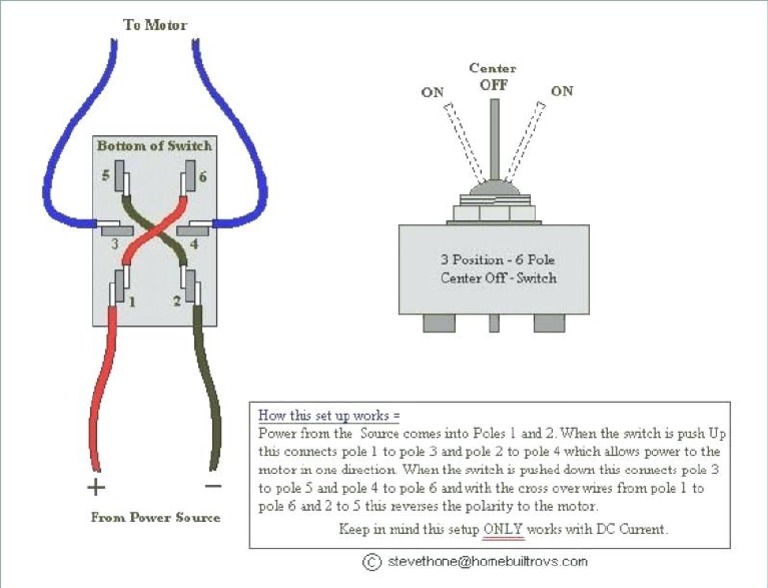
- A diagram for a toggle switch controlling a motor or other electrical device.
Understanding the circuitry of On Off On toggle switch wiring diagrams has practical applications in various fields, including electrical engineering, construction, and home maintenance. Electricians use these diagrams to design, install, and troubleshoot electrical systems. Construction workers rely on them to ensure that electrical installations comply with building codes. Homeowners can use them to safely repair or replace toggle switches in their homes.
In summary, the circuitry component of On Off On toggle switch wiring diagrams is crucial for understanding the electrical connections and ensuring the proper and safe operation of the switch. By studying these diagrams, individuals can gain valuable knowledge for various practical applications.
Connections
In the context of On Off On toggle switch wiring diagrams, the connections between the switch terminals and the other components play a critical role in determining the functionality and safety of the electrical circuit. The diagram specifies these connections in detail, ensuring that the switch operates correctly and that the electrical current flows safely through the circuit.
Real-life examples of connections in On Off On toggle switch wiring diagrams include:
- The connection between the switch terminal and the power source (usually the black wire).
- The connection between the switch terminal and the load (usually the red wire).
- The connection between the switch terminal and the neutral wire (usually the white wire).
Understanding these connections is essential for various practical applications, including:
- Installing and replacing toggle switches safely and correctly.
- Troubleshooting electrical problems related to toggle switches.
- Designing and modifying electrical circuits that incorporate toggle switches.
In summary, the connections between the switch terminals and the other components are a critical aspect of On Off On toggle switch wiring diagrams. Understanding these connections is essential for ensuring the proper and safe operation of the switch and the electrical circuit as a whole.
Terminal identification
Terminal identification is a critical component of On Off On Toggle Switch Wiring Diagrams because it provides essential information about the switch’s electrical connections. Without proper terminal identification, it would be difficult to determine which wires should be connected to which terminals, potentially leading to incorrect wiring and electrical hazards.
Real-life examples of terminal identification in On Off On Toggle Switch Wiring Diagrams include:
- Identifying the “line” terminal, which is connected to the power source.
- Identifying the “load” terminal, which is connected to the electrical device being controlled by the switch.
- Identifying the “common” terminal, which is often used for three-way switches and provides flexibility in wiring configurations.
Understanding terminal identification is essential for various practical applications, including:
- Installing toggle switches safely and correctly.
- Troubleshooting electrical problems related to toggle switches.
- Designing and modifying electrical circuits that incorporate toggle switches.
In summary, terminal identification is a critical aspect of On Off On Toggle Switch Wiring Diagrams, as it provides the necessary information for making proper electrical connections. Understanding terminal identification is essential for ensuring the safe and effective operation of toggle switches and electrical circuits.
Switch operation
Within the context of “On Off On Toggle Switch Wiring Diagram,” understanding switch operation is crucial for comprehending the switch’s functionality and ensuring proper installation and use. The diagram provides insights into the switch’s behavior in its three positions: on, off, and on.
- Contact Mechanism: Toggle switches utilize a spring-loaded contact mechanism that physically connects or disconnects electrical contacts when the switch is flipped. This mechanism enables the switch to control the flow of electricity.
- Electrical State: The diagram indicates the electrical state of the switch in each position. When the switch is “on,” the contacts are closed, allowing current to flow through the circuit. When the switch is “off,” the contacts are open, interrupting the current flow.
- Multiple Circuits: Some toggle switches have multiple poles, allowing them to control multiple circuits simultaneously. The diagram clarifies how each pole operates and the corresponding circuits it controls.
- Switch Rating: The diagram may specify the switch’s electrical rating, which indicates the maximum current it can safely handle. Understanding this rating is essential to prevent overloading and potential hazards.
In summary, the “Switch operation: The diagram explains how the switch operates, including its on, off, and on positions.” aspect of “On Off On Toggle Switch Wiring Diagram” provides valuable information about the switch’s behavior and electrical characteristics. By understanding how the switch operates, electricians and homeowners can ensure safe and effective installation and operation of toggle switches in various electrical circuits.
Load type
In the context of “On Off On Toggle Switch Wiring Diagram,” understanding the “Load type: The diagram specifies the type of load that the switch is intended to control.” aspect is crucial for ensuring the switch’s proper functionality and safety. The diagram provides essential information about the type of electrical load that the switch is designed to handle, which can vary depending on factors such as power requirements, voltage, and current draw.
- Electrical Characteristics: Load type diagrams specify the electrical characteristics of the intended load, such as voltage, amperage, and power factor. This information ensures that the switch can safely handle the electrical demands of the load without overheating or causing damage.
- Load Compatibility: Different types of loads, such as resistive, inductive, and capacitive loads, have unique electrical properties. The diagram indicates whether the switch is compatible with specific load types, preventing potential issues like arcing or premature switch failure.
- Circuit Protection: Load type diagrams may recommend appropriate circuit protection devices, such as fuses or circuit breakers, to safeguard the switch and the load from electrical overloads or short circuits.
- Wiring Considerations: The diagram may provide guidance on the appropriate wire gauge and type for connecting the switch to the load. This information ensures that the wires can safely carry the electrical current required by the load.
Understanding the load type in “On Off On Toggle Switch Wiring Diagram” is essential for selecting the correct switch for the intended application. It helps prevent mismatching between the switch’s capabilities and the load’s requirements, ensuring safe and reliable operation of the electrical circuit.
Wire gauge
Understanding the relationship between “Wire gauge: The diagram may specify the wire gauge that should be used for the connections.” and “On Off On Toggle Switch Wiring Diagram” is essential for ensuring the safe and effective operation of electrical circuits. The wire gauge, which refers to the thickness of the electrical wire, plays a critical role in determining the current-carrying capacity and resistance of the circuit.
In “On Off On Toggle Switch Wiring Diagram,” the specified wire gauge ensures that the wires used to connect the switch to the power source and the load are of appropriate thickness to handle the electrical current. Using wires that are too thin can lead to overheating, increased resistance, and potential fire hazards. Conversely, using wires that are too thick can be wasteful and unnecessary.
Real-life examples of wire gauge specifications in “On Off On Toggle Switch Wiring Diagram” include:
- A diagram for a single-pole, single-throw (SPST) toggle switch controlling a light fixture may specify a wire gauge of 14 AWG (American Wire Gauge) for the wires connecting the switch to the power source and the light fixture.
- A diagram for a three-way toggle switch controlling a light fixture from two different locations may specify a wire gauge of 12 AWG for the wires connecting the switches and the light fixture.
Understanding the importance of wire gauge in “On Off On Toggle Switch Wiring Diagram” has practical applications in various fields, including:
- Electrical engineers use this information to design and install safe and efficient electrical systems.
- Construction workers rely on it to ensure that electrical installations comply with building codes and safety standards.
- Homeowners can use it to safely repair or replace toggle switches and electrical wiring in their homes.
In summary, “Wire gauge: The diagram may specify the wire gauge that should be used for the connections.” is a critical component of “On Off On Toggle Switch Wiring Diagram” because it provides essential information for selecting the appropriate wire thickness based on the electrical current requirements of the circuit. Understanding this relationship is crucial for ensuring the safe and reliable operation of electrical systems.
Safety precautions
In the context of “On Off On Toggle Switch Wiring Diagram,” understanding “Safety precautions: The diagram may include safety precautions, such as the need to turn off the power before working on the circuit.” is paramount for preventing electrical accidents and ensuring the safety of individuals working on electrical circuits. These precautions provide critical instructions and warnings that guide proper handling and maintenance of electrical systems.
Real-life examples of safety precautions commonly found in “On Off On Toggle Switch Wiring Diagram” include:
- Warnings to turn off the power at the circuit breaker or fuse box before attempting any electrical work.
- Instructions to wear appropriate personal protective equipment (PPE), such as insulated gloves and safety glasses.
- Cautions to avoid contact with live wires or terminals.
- Reminders to use caution when working with electricity, as even low-voltage circuits can be hazardous.
Understanding and adhering to these safety precautions is crucial for various practical applications, including:
- Electricians and electrical contractors rely on these precautions to ensure their safety while installing, repairing, and maintaining electrical systems.
- Homeowners use them as a reference when performing basic electrical tasks, such as replacing light switches or installing ceiling fans.
- Educational institutions incorporate these precautions into their electrical engineering and vocational training programs to emphasize the importance of electrical safety.
In summary, “Safety precautions: The diagram may include safety precautions, such as the need to turn off the power before working on the circuit.” is an essential component of “On Off On Toggle Switch Wiring Diagram.” These precautions provide critical guidance for safe electrical practices, helping to prevent accidents, injuries, and potential hazards. Understanding and following these precautions is crucial for anyone working with or around electrical systems.
Troubleshooting
In the context of “On Off On Toggle Switch Wiring Diagram,” understanding “Troubleshooting: The diagram can be used for troubleshooting, helping to identify and fix problems with the switch or circuit.” is crucial for maintaining functional and safe electrical systems. The diagram serves as a valuable tool for diagnosing and resolving issues related to toggle switches and the electrical circuits they control.
A key reason why “Troubleshooting: The diagram can be used for troubleshooting, helping to identify and fix problems with the switch or circuit.” is a critical component of “On Off On Toggle Switch Wiring Diagram” lies in its ability to provide a visual representation of the electrical connections. By studying the diagram, electricians and homeowners can trace the flow of electricity through the circuit, identify potential points of failure, and pinpoint the source of problems.
Real-life examples of “Troubleshooting: The diagram can be used for troubleshooting, helping to identify and fix problems with the switch or circuit.” within “On Off On Toggle Switch Wiring Diagram” include:
- Diagnosing why a toggle switch is not turning on a light fixture by checking for loose connections or faulty wiring.
- Identifying a short circuit in the circuit by examining the diagram and tracing the electrical path.
- Determining the cause of a flickering light by analyzing the diagram and identifying potential issues with the switch or wiring.
The practical applications of understanding “Troubleshooting: The diagram can be used for troubleshooting, helping to identify and fix problems with the switch or circuit.” are extensive. Electricians rely on wiring diagrams to troubleshoot electrical problems in residential, commercial, and industrial settings. Homeowners can use them to safely diagnose and fix minor electrical issues in their own homes. Additionally, students and apprentices in electrical fields use wiring diagrams as a learning tool to develop their troubleshooting skills.
In summary, “Troubleshooting: The diagram can be used for troubleshooting, helping to identify and fix problems with the switch or circuit.” is a critical component of “On Off On Toggle Switch Wiring Diagram” as it provides a visual guide for diagnosing and resolving issues with toggle switches and electrical circuits. Understanding how to use wiring diagrams for troubleshooting is essential for ensuring the safe and efficient operation of electrical systems.
Customization
Within the realm of “On Off On Toggle Switch Wiring Diagram,” the aspect of “Customization: The diagram can be used as a starting point for customizing the circuit to meet specific needs.” holds significant relevance, as it empowers individuals to tailor electrical circuits to their unique requirements. This customization capability extends beyond the standard functionality of toggle switches, allowing for a wide range of modifications and enhancements.
- Component Selection: The diagram provides a framework for selecting appropriate electrical components, such as resistors, capacitors, and additional switches, to achieve desired circuit behavior.
- Circuit Modification: The diagram serves as a guide for modifying the circuit layout, adding or removing components, and altering connections to suit specific needs, such as controlling multiple lights with a single switch.
- Voltage and Current Adjustment: By understanding the circuit diagram, users can adjust voltage and current levels to match the requirements of the connected devices, ensuring optimal performance and safety.
- Integration with Other Systems: The diagram enables the integration of toggle switches with other electrical systems, such as home automation or security systems, allowing for remote control and enhanced functionality.
In summary, “Customization: The diagram can be used as a starting point for customizing the circuit to meet specific needs.” is a crucial aspect of “On Off On Toggle Switch Wiring Diagram” as it empowers users to modify and enhance electrical circuits to suit their unique requirements. This customization capability opens up a world of possibilities, from simple modifications to complex integrations, ultimately leading to more versatile and efficient electrical systems.
Code compliance
Within the context of “On Off On Toggle Switch Wiring Diagram,” understanding “Code compliance: The diagram can help ensure that the installation complies with electrical codes.” is crucial for ensuring the safety and reliability of electrical systems. Wiring diagrams serve as blueprints for electrical installations, providing detailed instructions on how to connect components and ensuring adherence to established electrical codes and standards.
- Safety Regulations: Wiring diagrams incorporate essential safety regulations, such as proper grounding techniques and circuit protection measures, to prevent electrical hazards like shock or fire.
- Material Specifications: The diagram specifies the types of electrical wires, switches, and other components that meet code requirements for current-carrying capacity, insulation, and durability.
- Inspection Approval: By following the wiring diagram, electricians can ensure that their installations meet the standards required for inspection and approval by electrical authorities.
- Insurance Coverage: Installations that comply with electrical codes are more likely to be covered by insurance in the event of an electrical accident or damage.
In summary, “Code compliance: The diagram can help ensure that the installation complies with electrical codes.” is a critical aspect of “On Off On Toggle Switch Wiring Diagram” as it provides a roadmap for safe and code-compliant electrical installations. Adherence to electrical codes not only ensures the safety of individuals but also protects property and minimizes the risk of electrical hazards.


![[DIAGRAM] On Off Toggle Switch Wiring Diagram](https://i0.wp.com/chematron.org/image/9-pin-low-off-high-trane-toggle-switch-wiring-diagram-14.jpg?w=665&ssl=1)


Related Posts


