Car electrical wiring diagrams are pictorial representations of a vehicle’s electrical system, showing the connections between components. They use symbols and lines to indicate the flow of electricity through wires, switches, relays, and other electrical devices.
Wiring diagrams are crucial for troubleshooting electrical problems, as they allow technicians to trace the flow of electricity and identify any faults in the system. For instance, if a headlight is not working, the wiring diagram will show which fuses, relays, and switches are involved in the circuit, allowing the technician to isolate and repair the problem quickly and efficiently.
The development of car electrical wiring diagrams is closely tied to the advancement of automotive electrical systems. As cars became more complex and electrical systems became more prevalent, the need for a standardized way to represent these systems became increasingly important. Today, wiring diagrams are an essential tool for anyone working on or repairing automotive electrical systems.
Understanding the essential aspects of “How To Read Car Electrical Wiring Diagrams” is crucial for anyone working on or repairing automotive electrical systems. These diagrams provide a visual representation of the electrical system, showing the connections between components and the flow of electricity. By understanding the key aspects of wiring diagrams, technicians can quickly and accurately troubleshoot electrical problems.
- Symbols: Wiring diagrams use standardized symbols to represent electrical components, such as batteries, switches, relays, and fuses.
- Lines: Lines in a wiring diagram represent the electrical connections between components.
- Colors: The colors of wires and lines in a wiring diagram often indicate their function or purpose.
- Labels: Components and wires in a wiring diagram are often labeled with numbers or letters to help identify them.
- Power and ground: Wiring diagrams show the flow of power from the battery to the various components in the electrical system.
- Fuses and relays: Wiring diagrams show the location of fuses and relays, which protect the electrical system from damage.
- Testing points: Wiring diagrams often include testing points, which allow technicians to check the voltage or continuity of a circuit.
- Troubleshooting: Wiring diagrams are essential for troubleshooting electrical problems, as they allow technicians to trace the flow of electricity and identify any faults.
- Repair: Wiring diagrams can be used to help repair electrical problems by showing the technician how to replace or repair faulty components.
- Modification: Wiring diagrams can also be used to modify electrical systems, such as adding new components or changing the wiring configuration.
These are just a few of the key aspects of car electrical wiring diagrams. By understanding these aspects, technicians can use wiring diagrams to troubleshoot, repair, and modify automotive electrical systems quickly and accurately.
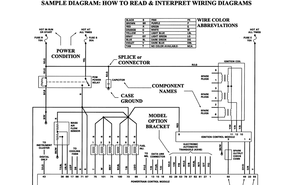
Symbols
Electrical system designs leverage standardized symbols within wiring diagrams to convey the relationships between components. These symbols form the foundation for understanding how to read car electrical wiring diagrams. Without the standardized symbols, wiring diagrams would be challenging to interpret, as they would require memorizing the specific representation for each component. This would make it difficult for technicians to quickly and accurately troubleshoot electrical problems.
Real-life examples of these symbols are prevalent throughout wiring diagrams. For instance, a battery is typically represented by a rectangle with two terminals, while a switch is depicted as a circle with two lines connecting to it. These symbols allow technicians to easily identify the function of each component in the electrical system.
The practical significance of understanding these symbols lies in their ability to enable efficient troubleshooting and repair of electrical systems. By recognizing the symbols and their corresponding components, technicians can trace the flow of electricity through the system, identify faulty components, and make necessary repairs. This understanding is essential for maintaining the proper functioning of a vehicle’s electrical system.
In summary, symbols are a critical component of car electrical wiring diagrams. They provide a standardized way to represent electrical components, enabling technicians to quickly and accurately understand the system’s design, troubleshoot problems, and make repairs. Without standardized symbols, wiring diagrams would be significantly more complex and challenging to use.
Lines
Lines within car electrical wiring diagrams play a crucial role in understanding how the electrical system functions. These lines serve as a visual representation of the electrical connections between various components, allowing technicians to trace the flow of electricity throughout the system. Without an accurate depiction of these connections, troubleshooting and repairing electrical problems would be significantly more challenging.
Real-life examples of these lines are evident throughout wiring diagrams. For instance, a line connecting a battery to a switch represents the electrical path through which power flows to operate the switch. Similarly, lines connecting a switch to a lightbulb indicate the circuit that controls the light’s operation.
The practical significance of understanding these lines lies in their ability to facilitate efficient troubleshooting and repair of electrical systems. By recognizing the connections between components, technicians can quickly identify the source of electrical problems and take appropriate corrective actions. This understanding is particularly important when dealing with complex electrical systems found in modern vehicles.
In summary, lines in car electrical wiring diagrams are essential for understanding the electrical system’s design and functionality. These lines provide a visual representation of the electrical connections between components, enabling technicians to trace the flow of electricity, troubleshoot problems, and make repairs effectively. Without a clear understanding of these lines, wiring diagrams would lose their significance in the realm of automotive electrical diagnostics.
Colors
Understanding the color coding of wires and lines in car electrical wiring diagrams is a crucial aspect of interpreting these diagrams accurately. Colors are often used to indicate the function or purpose of different electrical circuits, making it easier for technicians to identify and trace specific circuits within the system.
- Power and Ground Wires: Power wires, which carry current from the battery to various components, are typically colored red or orange. Ground wires, which provide a path for current to return to the battery, are usually black or brown.
- Circuit-Specific Colors: Different circuits in a vehicle’s electrical system may be assigned specific colors. For example, lighting circuits may use blue or green wires, while ignition circuits may use yellow or white wires.
- Manufacturer Standards: Car manufacturers often have their own color-coding standards for wiring diagrams. These standards ensure consistency across different models and years of vehicles from the same manufacturer.
- International Standards: In some cases, international standards may also be used for color coding. For example, the International Electrotechnical Commission (IEC) recommends using green/yellow wires for grounding.
Understanding the color coding of wires and lines in car electrical wiring diagrams is essential for accurate troubleshooting and repair. By recognizing the different colors and their associated functions, technicians can quickly identify and trace specific circuits, locate faulty components, and make necessary repairs.
Labels
In the context of “How to Read Car Electrical Wiring Diagrams”, the presence of labels on components and wires plays a critical role in understanding and interpreting these diagrams accurately. Labels provide vital information that aids technicians in identifying specific components and tracing their connections within the electrical system.
Real-life examples of labels in car electrical wiring diagrams are prevalent. Each component, such as a fuse, relay, or switch, is typically labeled with a unique number or letter. Additionally, wires are often color-coded and labeled to indicate their function and destination. These labels enable technicians to quickly identify the purpose of each component and trace the flow of electricity through the system.
The practical significance of understanding labels in car electrical wiring diagrams lies in its ability to facilitate efficient troubleshooting and repair. By recognizing the labels and their corresponding components, technicians can pinpoint problems, identify faulty connections, and make necessary repairs with greater accuracy and speed. This understanding is crucial for maintaining the proper functioning of a vehicle’s electrical system.
In summary, labels on components and wires serve as an essential element in “How to Read Car Electrical Wiring Diagrams”. They provide a systematic way to identify and trace components within the electrical system, enabling technicians to effectively troubleshoot and repair electrical problems. Without clear and accurate labels, wiring diagrams would be significantly more challenging to interpret and use, potentially leading to misdiagnoses and incorrect repairs.
Power and ground
In the context of “How to Read Car Electrical Wiring Diagrams”, understanding the flow of power in an electrical system is of paramount importance. Wiring diagrams provide a visual representation of this flow, enabling technicians to trace the path of electricity from the battery to various components and identify potential problems in the system.
- Battery: The battery serves as the primary source of power in a car’s electrical system. Wiring diagrams indicate the battery’s connection points and polarity, allowing technicians to ensure proper installation and maintenance.
- Fuses and Circuit Breakers: Fuses and circuit breakers protect electrical circuits from damage due to overcurrent conditions. Wiring diagrams show the location and amperage rating of these protective devices, enabling technicians to identify and replace faulty components.
- Ground: The ground connection provides a path for electrical current to return to the battery, completing the circuit. Wiring diagrams indicate the grounding points in the electrical system, allowing technicians to ensure proper grounding and prevent electrical faults.
- Loads: Loads represent the components that consume electrical power, such as lights, motors, and sensors. Wiring diagrams show the connections between loads and the power supply, enabling technicians to identify and troubleshoot issues related to power distribution.
By understanding the flow of power and ground in car electrical wiring diagrams, technicians can effectively diagnose and repair electrical problems, ensuring the proper functioning of the vehicle’s electrical system. These diagrams provide a comprehensive view of the electrical system, allowing technicians to trace the path of electricity, identify potential problems, and make informed decisions for repair and maintenance.
Fuses and relays
In the context of “How To Read Car Electrical Wiring Diagrams”, understanding the role of fuses and relays is crucial for comprehending the protective mechanisms within the electrical system. Wiring diagrams provide a visual representation of the location and function of these components, enabling technicians to identify and troubleshoot potential electrical faults effectively.
- Fuse Protection: Fuses are designed to interrupt the flow of excessive current in an electrical circuit, thereby protecting components from damage. Wiring diagrams indicate the location and amperage rating of fuses, allowing technicians to select and replace the correct fuse in the event of a blown fuse.
- Relay Operation: Relays are electromagnetic switches that control the flow of current in a circuit. Wiring diagrams show the location and function of relays, enabling technicians to identify and troubleshoot issues related to relay activation and operation.
- Circuit Protection: By isolating faulty circuits, fuses and relays prevent damage to other components and ensure the safety of the electrical system. Wiring diagrams provide insights into the specific circuits protected by fuses and relays, allowing technicians to trace and identify potential problems.
- Fault Diagnosis: Wiring diagrams help technicians diagnose electrical faults by indicating the location of fuses and relays. By checking the condition of these components, technicians can quickly identify potential problems and take appropriate corrective actions.
Understanding the location and function of fuses and relays through wiring diagrams is essential for maintaining a properly functioning electrical system in a car. These diagrams provide a comprehensive view of the electrical system’s protective mechanisms, enabling technicians to effectively troubleshoot and repair electrical faults, ensuring the safety and reliability of the vehicle.
Testing points
Within the context of “How To Read Car Electrical Wiring Diagrams”, testing points play a crucial role in facilitating effective troubleshooting and repair of electrical systems. Wiring diagrams provide technicians with the necessary information to locate these testing points, enabling them to perform voltage and continuity checks to assess the functionality of individual components and circuits.
Real-life examples of testing points within car electrical wiring diagrams are prevalent. These points are typically indicated by small circles or squares with labels that correspond to specific components or sections of the circuit. By connecting a voltmeter or continuity tester to these points, technicians can measure voltage levels, check for open circuits, and verify the proper flow of electricity.
The practical significance of understanding testing points in car electrical wiring diagrams lies in their ability to expedite the troubleshooting process. By utilizing these points, technicians can quickly identify faulty components or connections, reducing diagnostic time and minimizing unnecessary part replacements. This understanding is particularly valuable in complex electrical systems, where tracing problems can be challenging without a systematic approach.
In summary, testing points are an integral part of car electrical wiring diagrams, providing technicians with a means to verify the electrical integrity of components and circuits. Understanding the location and purpose of these testing points is a critical aspect of “How To Read Car Electrical Wiring Diagrams” and is essential for effective troubleshooting and repair of electrical systems.
Troubleshooting
Within the context of “How To Read Car Electrical Wiring Diagrams”, troubleshooting electrical problems is a critical aspect that relies heavily on the effective use of wiring diagrams. These diagrams provide a visual representation of the electrical system, allowing technicians to trace the flow of electricity and identify any faults that may arise.
- Component Identification: Wiring diagrams enable technicians to identify and locate specific components within the electrical system. By referencing the diagram, technicians can quickly determine the function and location of fuses, relays, switches, and other components, facilitating efficient troubleshooting.
- Circuit Tracing: Wiring diagrams allow technicians to trace the path of electrical circuits throughout the vehicle. By following the lines and symbols in the diagram, technicians can identify the origin and destination of each circuit, simplifying the process of fault isolation.
- Voltage and Continuity Testing: Wiring diagrams provide testing points where technicians can connect a voltmeter or continuity tester to measure voltage levels and check for open or short circuits. This testing helps identify faulty components or connections, expediting the troubleshooting process.
- Repair Guidance: Wiring diagrams guide technicians in repairing electrical faults by providing insights into the proper connections and component replacements. By referencing the diagram, technicians can ensure that repairs are made correctly, restoring the electrical system to its intended functionality.
In summary, the ability to read and interpret wiring diagrams is paramount for effective troubleshooting of car electrical problems. Wiring diagrams empower technicians to trace electrical circuits, identify faulty components, and make informed repair decisions, ensuring the proper functioning and safety of the vehicle’s electrical system.
Repair
Within the context of “How To Read Car Electrical Wiring Diagrams”, the ability to use these diagrams for repair purposes is a critical aspect of electrical system maintenance and troubleshooting. Wiring diagrams provide technicians with a visual representation of the electrical system, allowing them to identify faulty components and determine the appropriate repair procedures.
A key example of this relationship is the identification of blown fuses or faulty relays. Wiring diagrams indicate the location and amperage rating of fuses, enabling technicians to quickly identify and replace blown fuses. Similarly, wiring diagrams show the location and function of relays, allowing technicians to diagnose and replace faulty relays that may be interrupting electrical circuits.
The practical significance of understanding how to use wiring diagrams for repair lies in the efficient and accurate troubleshooting of electrical problems. By referencing the wiring diagram, technicians can trace electrical circuits, locate faulty components, and determine the appropriate repair procedures. This understanding reduces diagnostic time, minimizes unnecessary part replacements, and ensures the proper functioning of the electrical system.
In summary, the ability to repair electrical problems using wiring diagrams is an essential aspect of “How To Read Car Electrical Wiring Diagrams”. Wiring diagrams empower technicians to identify faulty components, determine repair procedures, and restore the electrical system to its intended functionality, ensuring the safety and reliability of the vehicle.
Modification
In the context of “How To Read Car Electrical Wiring Diagrams”, understanding how to modify electrical systems is a critical aspect for enthusiasts and professionals seeking to customize or upgrade their vehicles’ electrical components. Wiring diagrams provide a visual representation of the electrical system, allowing users to make informed decisions about adding new components or altering the existing wiring configuration.
A key example of this relationship is the installation of aftermarket accessories, such as audio systems or performance upgrades. By referencing the wiring diagram, users can identify suitable connection points, ensuring compatibility and avoiding potential electrical hazards. Additionally, wiring diagrams are essential for troubleshooting modifications, as they provide insights into the modified circuits and components.
The practical significance of understanding how to modify electrical systems using wiring diagrams lies in the ability to personalize and enhance the vehicle’s electrical capabilities. It empowers users to integrate new technologies, improve system performance, and cater to specific electrical requirements.
In summary, the ability to modify electrical systems using wiring diagrams is an essential aspect of “How To Read Car Electrical Wiring Diagrams”. Wiring diagrams empower users to make informed decisions about electrical modifications, ensuring compatibility, safety, and optimal performance of the vehicle’s electrical system.


Related Posts


