7.3 Powerstroke IDM Wiring Diagram
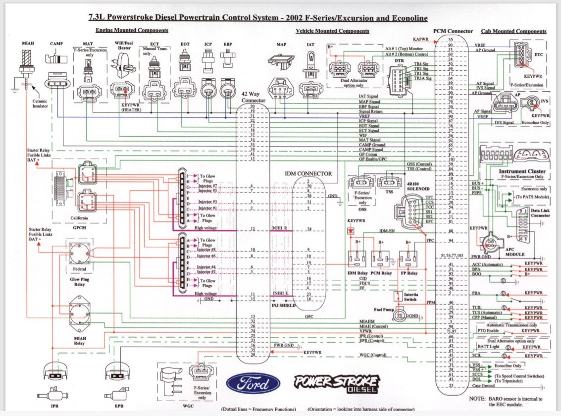
A 7.3 Powerstroke IDM Wiring Diagram outlines the electrical connections between the Injector Driver Module (IDM) and other components in a 7.3-liter Powerstroke diesel engine. The IDM is responsible for controlling the timing and duration of fuel injection, ensuring optimal engine performance and efficiency.
The diagram provides a visual representation of the wiring harness, connectors, and sensors associated with the IDM. It aids technicians in troubleshooting electrical issues, diagnosing faults, and performing repairs. By understanding the wiring connections, technicians can identify potential points of failure and take preventive measures to ensure reliable engine operation.
The 7.3 Powerstroke IDM Wiring Diagram is a crucial tool for maintaining and servicing 7.3-liter Powerstroke diesel engines. It provides a comprehensive overview of the electrical system, enabling technicians to diagnose and resolve electrical problems efficiently. As advanced engine technologies continue to emerge, wiring diagrams remain essential references for understanding the complex electrical systems in modern vehicles.
7.3 Powerstroke IDM Wiring Diagram: Essential Aspects
Understanding the essential aspects of a 7.3 Powerstroke IDM Wiring Diagram is crucial for maintaining and servicing 7.3-liter Powerstroke diesel engines. These diagrams provide a comprehensive overview of the electrical connections between the Injector Driver Module (IDM) and other components in the engine, enabling technicians to diagnose and resolve electrical problems efficiently.
- Circuit Identification: Diagrams clearly identify each electrical circuit associated with the IDM, including power supply, ground connections, sensor inputs, and injector outputs.
- Connector Pinouts: Diagrams specify the pin assignments for each connector, ensuring proper connection of wires and components.
- Sensor Locations: Diagrams indicate the physical location of sensors connected to the IDM, aiding in troubleshooting and replacement procedures.
- Wire Color Coding: Diagrams use color-coded wires to simplify circuit tracing and identification.
- Grounding Points: Diagrams show the grounding points for the IDM and associated components, ensuring proper electrical continuity.
- Fuse and Relay Locations: Diagrams identify the location of fuses and relays related to the IDM, enabling quick access for troubleshooting and replacement.
- Troubleshooting Guide: Some diagrams include a troubleshooting guide that provides diagnostic steps for common electrical issues.
- Component Identification: Diagrams help identify and locate specific components connected to the IDM, such as sensors, actuators, and solenoids.
- Compatibility Information: Diagrams may specify the compatibility of the wiring harness with different engine variants and model years.
- Compliance Standards: Diagrams ensure compliance with industry standards and regulations related to electrical installations.
Conclusion:
These essential aspects of a 7.3 Powerstroke IDM Wiring Diagram make it an indispensable tool for technicians. By providing a comprehensive visual representation of the electrical system, diagrams enable efficient troubleshooting, accurate repairs, and preventive maintenance. Understanding these aspects is key to ensuring reliable operation and performance of 7.3-liter Powerstroke diesel engines.
Circuit Identification
Circuit identification plays a pivotal role in understanding the electrical system of a 7.3 Powerstroke diesel engine. The wiring diagram clearly outlines each electrical circuit associated with the Injector Driver Module (IDM), providing a comprehensive overview of the power supply, ground connections, sensor inputs, and injector outputs. This information is crucial for troubleshooting electrical issues, performing repairs, and ensuring optimal engine performance.
- Power Supply Identification: The diagram specifies the power supply connections to the IDM, indicating the source of electrical power and the voltage requirements. This information is essential for ensuring proper voltage supply to the IDM and its associated components.
- Ground Connections: Proper grounding is crucial for the electrical system to function correctly. The wiring diagram identifies the grounding points for the IDM and related components, ensuring that electrical circuits are properly completed and electrical noise is minimized.
- Sensor Input Identification: The diagram outlines the sensor inputs connected to the IDM. These sensors provide vital information about engine parameters such as crankshaft position, camshaft position, and fuel pressure. Understanding these sensor connections is necessary for diagnosing sensor-related issues and ensuring accurate engine control.
- Injector Output Identification: The wiring diagram specifies the injector output connections from the IDM to the fuel injectors. This information is essential for troubleshooting injector-related problems and ensuring proper fuel delivery to the engine’s cylinders.
In conclusion, circuit identification in a 7.3 Powerstroke IDM Wiring Diagram provides a comprehensive understanding of the electrical system. By clearly identifying each electrical circuit, including power supply, ground connections, sensor inputs, and injector outputs, technicians can efficiently diagnose electrical issues, perform accurate repairs, and maintain optimal engine performance.
Connector Pinouts
The intricate relationship between connector pinouts and 7.3 Powerstroke IDM Wiring Diagrams is paramount for the proper functioning of the electrical system in these diesel engines. Connector pinouts are critical components of the wiring diagram, providing detailed information about the assignment of each pin within the connectors. This information is essential for ensuring the correct connection of wires and components throughout the electrical system.
Without accurate connector pinouts, technicians would face significant challenges in troubleshooting electrical issues and performing repairs. Incorrectly connected wires can lead to a myriad of problems, ranging from minor malfunctions to catastrophic failures. The wiring diagram serves as a guide, ensuring that each wire is connected to the correct pin on each connector, preventing potential electrical hazards and ensuring optimal engine performance.
For instance, consider the fuel injector connector. The wiring diagram specifies the pin assignments for the power supply, ground connection, and signal wire for each injector. If these wires are not properly connected to the correct pins on the injector connector, the fuel injector may not function correctly, leading to engine performance issues. Similarly, incorrect pin connections for sensors, actuators, and other components can result in various electrical problems.
The practical applications of understanding connector pinouts are evident in the daily work of technicians and mechanics. When diagnosing electrical issues, technicians rely on wiring diagrams to identify the correct pin connections for testing and troubleshooting. Accurate pinout information enables them to quickly isolate and resolve electrical problems, minimizing downtime and ensuring efficient engine operation.
In summary, connector pinouts form a critical component of 7.3 Powerstroke IDM Wiring Diagrams, providing essential information for the proper connection of wires and components. Understanding these pinouts is crucial for maintaining optimal engine performance, preventing electrical hazards, and ensuring efficient troubleshooting and repair procedures.
Sensor Locations
The connection between sensor locations and 7.3 Powerstroke IDM Wiring Diagrams is pivotal in understanding the electrical system and ensuring optimal engine performance. Wiring diagrams provide detailed information about the physical location of sensors connected to the Injector Driver Module (IDM), which plays a critical role in controlling fuel injection timing and duration.
Knowing the exact location of sensors is crucial for efficient troubleshooting and replacement procedures. When an engine encounters issues related to fuel injection or sensor malfunctions, technicians rely on wiring diagrams to identify the sensor’s physical location. This information allows them to quickly access the sensor, perform necessary tests, and replace it if required.
For instance, consider a scenario where the engine experiences rough idling or poor fuel economy. By referring to the wiring diagram, a technician can determine the location of the crankshaft position sensor, which provides vital information about engine speed and timing. With the sensor’s location identified, the technician can swiftly inspect the sensor’s connection, check its signal output, and replace it if necessary, restoring optimal engine performance.
Moreover, understanding sensor locations is essential for preventive maintenance and routine inspections. Technicians can proactively inspect sensor connections, check for corrosion or damage, and ensure proper sensor mounting to prevent potential issues. This proactive approach helps minimize downtime and extends the lifespan of the engine and its components.
In summary, sensor locations play a critical role in 7.3 Powerstroke IDM Wiring Diagrams, providing valuable information for troubleshooting, replacement procedures, and preventive maintenance. By understanding the physical location of sensors connected to the IDM, technicians can efficiently diagnose and resolve electrical issues, ensuring optimal engine performance and longevity.
Wire Color Coding
Within the intricate landscape of a 7.3 Powerstroke IDM Wiring Diagram, wire color coding plays a crucial role in simplifying circuit tracing and identification, enabling technicians and enthusiasts to navigate the electrical system with greater ease and precision. This color-coding system provides a visual cue, assigning specific colors to different types of circuits or functions, making it easier to distinguish between them during installation, troubleshooting, and repairs.
- Circuit Type Differentiation: Color coding helps differentiate between various circuit types, such as power, ground, sensor inputs, and actuator outputs. For instance, power wires may be designated as red, while ground wires are often black or brown, simplifying the identification of critical circuits.
- Functional Grouping: Similar functions are often grouped together using consistent wire colors. For example, all injector wires may be color-coded in a specific pattern, allowing for quick identification and tracing of injector-related circuits.
- Component Identification: Color coding assists in identifying specific components within the system. For instance, a blue wire may consistently connect to temperature sensors, making it easier to locate and diagnose sensor-related issues.
- Simplified Troubleshooting: When troubleshooting electrical problems, color coding enables technicians to quickly isolate the affected circuit by visually tracing the colored wires. This reduces diagnostic time and minimizes the likelihood of misidentification.
In summary, wire color coding in 7.3 Powerstroke IDM Wiring Diagrams simplifies circuit tracing and identification, providing a valuable tool for electrical system maintenance and troubleshooting. By assigning specific colors to different circuit types, functions, and components, technicians can navigate the electrical system more efficiently, reducing downtime and ensuring optimal engine performance.
Grounding Points
Within the intricate schematics of a 7.3 Powerstroke IDM Wiring Diagram, grounding points play a pivotal role in establishing and maintaining proper electrical continuity throughout the system. These diagrams meticulously depict the specific locations where the Injector Driver Module (IDM) and its associated components connect to the vehicle’s electrical ground. Understanding these grounding points is paramount for ensuring reliable electrical operation and optimal engine performance.
- Chassis Grounding: The chassis of the vehicle provides a crucial grounding reference for the IDM and its associated components. Wiring diagrams indicate the specific points where the IDM and related modules connect to the chassis, ensuring a robust electrical connection to the ground plane.
- Engine Block Grounding: The engine block serves as another important grounding point for the IDM system. Diagrams show the locations where the IDM and its components ground to the engine block, creating a low-resistance path for electrical current to flow.
- Dedicated Grounding Wires: In addition to chassis and engine block grounding, dedicated grounding wires may be used to connect the IDM and its components to specific grounding points. Diagrams illustrate the routing and termination points of these dedicated grounding wires, ensuring proper electrical continuity.
- Ground Loop Prevention: Proper grounding practices are essential to prevent ground loops, which can cause electrical noise and interference within the system. Wiring diagrams help identify potential ground loops and provide guidance on how to avoid them by ensuring that all components share a common ground reference.
In conclusion, grounding points play a vital role in 7.3 Powerstroke IDM Wiring Diagrams. By precisely indicating the locations where the IDM and associated components connect to the vehicle’s electrical ground, these diagrams enable technicians to establish and maintain proper electrical continuity throughout the system. This ensures reliable electrical operation, minimizes electrical noise and interference, and contributes to optimal engine performance.
Fuse and Relay Locations
Within the intricate network of a 7.3 Powerstroke IDM Wiring Diagram, fuse and relay locations play a critical role in ensuring the proper functioning and protection of the Injector Driver Module (IDM) and its associated components. These diagrams provide a detailed visual guide to the placement of fuses and relays within the electrical system, empowering technicians and enthusiasts to quickly identify, troubleshoot, and replace these vital components.
Fuses and relays serve as essential safeguards within the electrical system, protecting against overcurrent and electrical faults. Fuses are designed to break the circuit and prevent damage in the event of excessive current flow, while relays act as electronically controlled switches, allowing for the activation and deactivation of circuits.
The 7.3 Powerstroke IDM Wiring Diagram meticulously outlines the location of each fuse and relay associated with the IDM system. This information is crucial for efficient troubleshooting and repair procedures. For instance, if an electrical fault occurs within the IDM system, technicians can swiftly refer to the wiring diagram to identify the affected fuse or relay. With the precise location known, they can promptly replace the faulty component, restoring electrical functionality and minimizing downtime.
Moreover, understanding fuse and relay locations is essential for preventive maintenance and routine inspections. By regularly checking the condition of fuses and relays, technicians can proactively identify and replace aging or damaged components before they cause electrical issues. This proactive approach helps extend the lifespan of the electrical system and ensures optimal engine performance.
In summary, fuse and relay locations are critical components of 7.3 Powerstroke IDM Wiring Diagrams. These diagrams provide a comprehensive visual guide to the placement of fuses and relays within the electrical system. By understanding the location of these vital components, technicians can efficiently troubleshoot electrical faults, perform timely repairs, and conduct preventive maintenance, ensuring the reliable operation of the IDM system and optimal engine performance.
Troubleshooting Guide
Within the realm of 7.3 Powerstroke IDM Wiring Diagrams, the inclusion of a troubleshooting guide holds immense significance for technicians and enthusiasts alike. This guide provides a structured approach to diagnosing common electrical issues, empowering users to identify and resolve problems efficiently and effectively.
The troubleshooting guide is a valuable companion to the wiring diagram, offering step-by-step instructions for diagnosing electrical faults. It systematically leads users through a series of tests and measurements, isolating potential causes and guiding them towards a solution. By following the troubleshooting guide, technicians can narrow down the source of the problem, saving time and effort compared to haphazard troubleshooting methods.
Real-life examples of the troubleshooting guide’s practical applications abound. Consider a scenario where the engine experiences rough idling or poor fuel economy. The troubleshooting guide can assist in diagnosing potential issues related to the IDM, injector circuits, or sensor inputs. By following the guide’s diagnostic steps, technicians can systematically eliminate possible causes, ultimately pinpointing the root of the problem.
The practical significance of understanding the troubleshooting guide cannot be overstated. It empowers technicians with the knowledge and tools to resolve electrical issues independently, reducing downtime and minimizing the need for costly repairs. Moreover, the troubleshooting guide promotes a deeper understanding of the IDM system, enabling technicians to make informed decisions and proactively maintain the electrical system.
In summary, the inclusion of a troubleshooting guide in 7.3 Powerstroke IDM Wiring Diagrams is a critical resource for troubleshooting common electrical issues. By providing a structured approach to diagnosing faults, the troubleshooting guide empowers users to identify and resolve problems efficiently, saving time, effort, and expense. Its practical applications extend to a wide range of electrical issues, making it an invaluable tool for maintaining optimal engine performance and ensuring reliable operation.
Component Identification
Within the intricate schematics of a 7.3 Powerstroke IDM Wiring Diagram, component identification plays a crucial role in understanding the electrical system and ensuring optimal engine performance. These diagrams meticulously depict the specific components connected to the Injector Driver Module (IDM), including sensors, actuators, and solenoids, providing valuable information for troubleshooting, maintenance, and repairs.
- Sensor Identification: Wiring diagrams clearly identify the sensors connected to the IDM, such as the crankshaft position sensor, camshaft position sensor, and fuel pressure sensor. This information is essential for diagnosing sensor-related issues, ensuring accurate engine control, and maintaining optimal fuel efficiency.
- Actuator Identification: Diagrams also identify actuators connected to the IDM, such as the fuel injector solenoid and the turbocharger boost control solenoid. Understanding the location and function of these actuators is critical for troubleshooting electrical faults and ensuring proper engine operation.
- Solenoid Identification: Wiring diagrams help locate solenoids within the IDM system, such as the starter solenoid and the transmission shift solenoid. This information is valuable for diagnosing electrical issues related to starting the engine or shifting gears, minimizing downtime and ensuring a smooth driving experience.
- Real-Life Example: Consider a scenario where the engine experiences rough idling or poor fuel economy. By referring to the wiring diagram and identifying the location of the fuel injector solenoid, a technician can quickly test its functionality and determine if it needs to be replaced, restoring optimal engine performance.
In summary, component identification in 7.3 Powerstroke IDM Wiring Diagrams provides a comprehensive understanding of the electrical system’s components. By precisely indicating the location and function of sensors, actuators, and solenoids, these diagrams empower technicians and enthusiasts to efficiently troubleshoot electrical faults, perform timely repairs, and ensure optimal engine performance throughout the vehicle’s lifespan.
Compatibility Information
Wiring diagrams for the 7.3 Powerstroke IDM play a critical role in ensuring the compatibility of the wiring harness with different engine variants and model years. This information is crucial for technicians and enthusiasts working on these engines, as it allows them to determine whether a particular wiring harness is suitable for their specific vehicle.
For instance, consider a scenario where a technician is replacing the wiring harness on a 1999 7.3 Powerstroke engine. By referring to the wiring diagram, the technician can verify that the new harness is compatible with the engine’s year and variant. This compatibility check helps to prevent potential issues that could arise from using an incompatible harness, such as electrical faults or performance problems.
Understanding the compatibility information provided in 7.3 Powerstroke IDM Wiring Diagrams is essential for ensuring proper electrical system operation. By carefully matching the wiring harness to the specific engine variant and model year, technicians can avoid costly mistakes and ensure that the engine runs smoothly and efficiently.
Compliance Standards
In the realm of 7.3 Powerstroke IDM Wiring Diagrams, compliance standards play a central role in ensuring the safety and reliability of electrical installations. These diagrams adhere to industry-defined guidelines and regulations to guarantee that electrical systems meet specific performance and safety requirements.
- National Electrical Code (NEC) Compliance: Wiring diagrams for 7.3 Powerstroke engines must comply with the NEC, a comprehensive set of regulations governing electrical installations in the United States. NEC compliance ensures that electrical systems meet minimum safety standards, reducing the risk of electrical fires, shocks, and other hazards.
- Automotive Industry Standards: Wiring diagrams also align with automotive industry standards, such as those set by the Society of Automotive Engineers (SAE). These standards ensure that electrical systems are designed and installed according to best practices, promoting reliable operation and longevity.
- Manufacturer’s Specifications: Wiring diagrams adhere to the specific electrical system design and specifications outlined by the engine manufacturer. This compliance ensures that the wiring harness and electrical components are compatible with the engine and its control systems, preventing potential issues and ensuring optimal performance.
- Emissions Regulations: In some regions, electrical installations must comply with emissions regulations. Wiring diagrams take into account these regulations, ensuring that the electrical system does not interfere with emission control devices and meets environmental standards.
By adhering to compliance standards, 7.3 Powerstroke IDM Wiring Diagrams empower technicians and enthusiasts to create safe and reliable electrical installations. These diagrams serve as a valuable resource for ensuring that electrical systems meet industry best practices, manufacturer specifications, and regulatory requirements.


Related Posts


