A 6 Prong Lawn Mower Ignition Switch Wiring Diagram depicts the electrical connections and components involved in starting a lawn mower engine. It outlines the wiring scheme for the ignition key switch, safety switches, battery, spark plug, and starter motor, enabling the flow of electricity to initiate combustion in the engine’s cylinders.
This wiring diagram is crucial for understanding the proper installation and repair of lawn mower ignition systems. By following its guidelines, users can ensure a safe and reliable starting mechanism for their equipment. Benefits include simplified troubleshooting, enhanced performance, and extended lifespan of the lawn mower.
Historically, the development of electronic ignition systems in lawn mowers has significantly improved their starting reliability and reduced maintenance requirements. This transition from mechanical to electronic ignition systems has revolutionized the way lawn mowers operate, paving the way for further advancements in the industry.
The phrase “6 Prong Lawn Mower Ignition Switch Wiring Diagram” refers to the technical instructions depicting the electrical connections and components involved in starting a lawn mower engine. It is a noun phrase representing a specific type of wiring diagram, and its key aspects are essential for understanding how lawn mower ignition systems operate and are repaired.
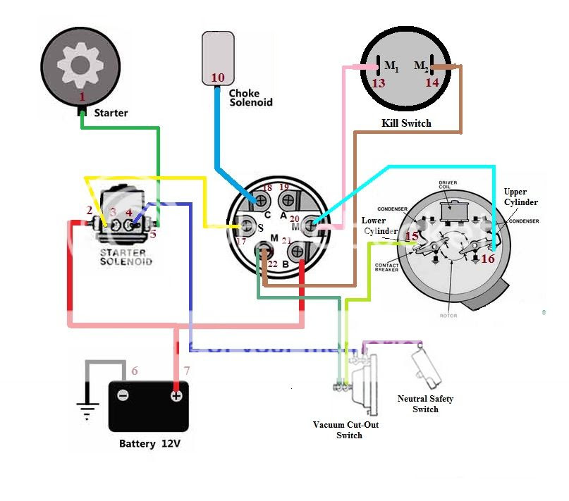
- Components: The diagram identifies the ignition key switch, safety switches, battery, spark plug, and starter motor, as well as their connections.
- Wiring: It outlines the electrical connections between these components, showing the flow of electricity to initiate combustion.
- Safety: The diagram includes safety switches that prevent the engine from starting if certain conditions are not met, such as the operator being in the correct position.
- Troubleshooting: The diagram assists in diagnosing and repairing ignition problems by providing a visual representation of the system.
- Installation: It guides the installation of a new ignition switch or wiring harness by providing detailed instructions.
- Maintenance: The diagram aids in regular maintenance tasks, such as cleaning and inspecting the ignition system components.
- Performance: By ensuring proper electrical connections, the diagram helps optimize lawn mower engine performance.
- Safety: Following the diagram’s guidelines reduces the risk of electrical accidents and ensures safe operation.
- Cost savings: By enabling DIY repairs and maintenance, the diagram can save on professional service costs.
These key aspects collectively provide a comprehensive understanding of a 6 Prong Lawn Mower Ignition Switch Wiring Diagram, its components, function, and relevance in lawn mower operation and maintenance.
Components
The identification of these components and their connections is a critical aspect of a 6 Prong Lawn Mower Ignition Switch Wiring Diagram. The components listed are essential elements of the ignition system, each playing a specific role in starting the lawn mower engine. The ignition key switch provides the initial activation, while safety switches prevent accidental starting. The battery supplies electrical power, the spark plug generates the ignition spark, and the starter motor engages the engine’s flywheel to initiate rotation.
Understanding the connections between these components is crucial for troubleshooting and repairing ignition problems. For instance, if the engine fails to start, the wiring diagram can guide the user in checking the continuity of the circuit, ensuring proper electrical flow from the battery to the spark plug.
In summary, the detailed identification and depiction of the ignition key switch, safety switches, battery, spark plug, and starter motor, along with their connections, are foundational elements of a 6 Prong Lawn Mower Ignition Switch Wiring Diagram. This information empowers users to understand, diagnose, and maintain their lawn mower’s ignition system effectively.
Wiring
The intricate electrical connections depicted in a 6 Prong Lawn Mower Ignition Switch Wiring Diagram are fundamental to understanding the ignition process. This wiring scheme outlines the precise connections between the ignition key switch, safety switches, battery, spark plug, and starter motor, revealing the path of electrical flow that initiates combustion in the engine’s cylinders.
The ignition key switch serves as the starting point for this electrical journey. When turned to the “on” position, it completes the circuit, allowing electricity to flow from the battery through the safety switches. These switches prevent the engine from starting if certain safety conditions are not met, such as the operator being in the correct position or the blade being disengaged. The electricity then continues through the ignition coil, which amplifies the voltage and directs it to the spark plug.
At the spark plug, the high-voltage electricity jumps across the gap between the electrodes, creating a spark that ignites the air-fuel mixture within the combustion chamber. This spark triggers a controlled explosion, driving the piston downward and initiating the engine’s power cycle. The starter motor, powered by the battery, engages the engine’s flywheel to provide the initial rotation necessary for the combustion process to begin.
Understanding the wiring and electrical connections in a 6 Prong Lawn Mower Ignition Switch Wiring Diagram is essential for troubleshooting and repairing ignition problems. By tracing the flow of electricity through the circuit, users can identify any breaks or malfunctions that prevent the engine from starting or running properly.
In summary, the wiring outlined in a 6 Prong Lawn Mower Ignition Switch Wiring Diagram is a critical component for comprehending the ignition process, diagnosing ignition issues, and maintaining optimal engine performance.
Safety
In the context of a 6 Prong Lawn Mower Ignition Switch Wiring Diagram, safety is a paramount consideration. The diagram incorporates safety switches to prevent inadvertent engine starts, enhancing operator safety and mitigating potential accidents.
-
Seat Switch
The seat switch is designed to prevent the engine from starting unless the operator is seated in the correct position. This feature ensures that the operator is in control of the mower before it is engaged, reducing the risk of injury from accidental blade contact. -
Blade Engagement Switch
The blade engagement switch prevents the engine from starting if the mower blade is engaged. This safety measure guards against accidental blade activation while starting the mower, reducing the risk of severe injury. -
Ground Fault Circuit Interrupter (GFCI)
Some lawn mowers incorporate a GFCI to protect against electrical shock hazards. The GFCI monitors the electrical current flow and quickly interrupts the circuit if an imbalance is detected, preventing potential electrocution. -
Engine Stop Switch
The engine stop switch provides a quick and accessible means to shut off the engine in case of an emergency. This switch is typically located on the mower’s handlebars, allowing the operator to react swiftly to potential hazards.
These safety switches are essential components of a 6 Prong Lawn Mower Ignition Switch Wiring Diagram, prioritizing operator safety and preventing accidents. By understanding their function and proper operation, users can ensure the safe and responsible use of their lawn mowers.
Troubleshooting
The 6 Prong Lawn Mower Ignition Switch Wiring Diagram serves as an essential tool in troubleshooting and repairing ignition problems by providing a visual representation of the system. It enables users to trace the electrical connections and identify any discrepancies, malfunctions, or areas of concern.
Real-life examples of troubleshooting using the diagram include:
- Diagnosing a faulty ignition switch by testing the continuity of the circuit.
- Identifying a break in the wiring harness by visually inspecting the diagram and tracing the wires.
- Troubleshooting a malfunctioning safety switch by checking the switch’s operation and connections.
The practical significance of understanding the connection between troubleshooting and the wiring diagram lies in the ability to perform repairs independently, saving time and expenses on professional services. It empowers users with the knowledge to maintain their lawn mowers effectively, ensuring optimal performance and longevity.
In summary, the troubleshooting aspect of the 6 Prong Lawn Mower Ignition Switch Wiring Diagram is a crucial component, providing a visual guide for diagnosing and repairing ignition problems. This understanding empowers users to maintain their lawn mowers efficiently and cost-effectively.
Installation
Within the context of a 6 Prong Lawn Mower Ignition Switch Wiring Diagram, the aspect of “Installation: It guides the installation of a new ignition switch or wiring harness by providing detailed instructions.” holds significant importance. This section of the diagram provides step-by-step instructions, enabling users to replace or install new ignition components or the entire wiring harness with precision and efficiency.
-
Component Identification
The diagram clearly identifies the various components involved in the ignition system, including the ignition switch, safety switches, battery, spark plug, and starter motor. This identification aids in locating and replacing specific components during the installation process.
-
Wiring Schematics
Detailed wiring schematics are included in the diagram, illustrating the proper connections between all components. These schematics guide users in correctly connecting the wires, ensuring a functional ignition system.
-
Safety Precautions
The installation instructions emphasize safety precautions that must be observed during the installation process. These precautions include disconnecting the battery, wearing appropriate safety gear, and following proper handling procedures.
-
Troubleshooting Tips
The diagram may also include troubleshooting tips to assist users in resolving common installation issues. These tips provide guidance on identifying and rectifying potential problems during the installation process.
Understanding the installation aspect of a 6 Prong Lawn Mower Ignition Switch Wiring Diagram empowers users to perform the task independently, saving on professional installation costs. By following the detailed instructions and adhering to safety guidelines, users can ensure a properly functioning ignition system, optimizing lawn mower performance and longevity.
Maintenance
Within the context of “6 Prong Lawn Mower Ignition Switch Wiring Diagram,” the aspect of “Maintenance: The diagram aids in regular maintenance tasks, such as cleaning and inspecting the ignition system components.” plays a crucial role in ensuring the longevity and optimal performance of the engine.
-
Identifying Components for Inspection
The wiring diagram provides a visual representation of the ignition system, allowing users to identify all components that require regular maintenance. This includes the ignition switch, safety switches, battery, spark plug, and starter motor.
-
Understanding Cleaning Procedures
The diagram helps users understand the proper cleaning procedures for each component. For example, it may indicate the use of specific cleaning agents or techniques to remove dirt, debris, or corrosion.
-
Early Detection of Issues
Regular maintenance, guided by the wiring diagram, enables users to detect potential issues early on. By inspecting the components and their connections, users can identify loose wires, damaged insulation, or signs of wear and tear, allowing for prompt repairs and preventing more significant problems.
-
Optimizing Performance
Regular maintenance tasks, facilitated by the wiring diagram, contribute to optimizing the performance of the ignition system. Clean and properly functioning components ensure efficient electrical flow, leading to improved starting, smoother operation, and increased fuel efficiency.
In summary, the “Maintenance: The diagram aids in regular maintenance tasks, such as cleaning and inspecting the ignition system components.” aspect of a 6 Prong Lawn Mower Ignition Switch Wiring Diagram empowers users to maintain their equipment effectively, minimize downtime, and extend the lifespan of their lawn mowers.
Performance
A 6 Prong Lawn Mower Ignition Switch Wiring Diagram is critical for optimizing lawn mower engine performance due to its role in ensuring proper electrical connections. Proper wiring guarantees that electrical current flows efficiently from the battery to the ignition switch, safety switches, spark plug, and starter motor, facilitating a smooth starting process and optimal engine operation.
For instance, a faulty ignition switch can lead to intermittent engine starts or complete failure to start. The wiring diagram aids in troubleshooting such issues by allowing users to check the continuity of electrical connections, detect loose wires, and identify any damaged components. By resolving these electrical faults, the diagram helps restore proper electrical flow and optimizes engine performance.
Furthermore, ensuring proper electrical connections minimizes electrical resistance, which can hinder the flow of current and result in decreased engine power and efficiency. The wiring diagram provides a clear visual representation of the electrical connections, enabling users to identify areas where resistance may occur. By addressing these issues and maintaining proper electrical connections, users can maximize engine performance and extend the lifespan of the lawn mower.
In summary, a 6 Prong Lawn Mower Ignition Switch Wiring Diagram plays a crucial role in optimizing lawn mower engine performance by ensuring proper electrical connections. By facilitating efficient electrical flow and minimizing resistance, the diagram helps users troubleshoot and resolve electrical issues, leading to a smooth starting process, enhanced engine power, and improved overall performance.
Safety
In the context of a “6 Prong Lawn Mower Ignition Switch Wiring Diagram”, safety plays a paramount role. Adhering to the diagram’s guidelines helps prevent electrical accidents, safeguarding the user and ensuring the safe operation of the lawn mower. This aspect of the diagram encompasses several key considerations:
-
Proper Connections
The diagram provides a detailed layout of the electrical connections, ensuring proper wiring and minimizing the risk of short circuits or electrical fires. Correctly connecting the ignition switch, safety switches, battery, and other components as per the diagram reduces the potential for electrical hazards.
-
Grounding
The diagram often includes grounding instructions, which are crucial for electrical safety. Grounding provides a path for excess electrical current to flow safely into the earth, preventing voltage spikes or shocks that could harm the user or damage components.
-
Component Quality
The diagram specifies the recommended components for the ignition system, ensuring their compatibility and adherence to safety standards. Using high-quality components reduces the risk of electrical failures or malfunctions that could lead to accidents.
-
Safety Switch Functionality
Safety switches, such as the seat switch and blade engagement switch, are crucial safety features. The diagram ensures their proper wiring and functionality, preventing the engine from starting if the operator is not in the correct position or if the blade is engaged. This reduces the risk of accidents and injuries during operation.
By following the guidelines outlined in the “6 Prong Lawn Mower Ignition Switch Wiring Diagram”, users can mitigate electrical hazards, enhance safety, and ensure the reliable operation of their lawn mowers. Ignoring or altering the diagram’s instructions can compromise safety and increase the risk of accidents or damage to the equipment.
Cost savings
A “6 Prong Lawn Mower Ignition Switch Wiring Diagram” empowers users with the knowledge and guidance to perform DIY repairs and maintenance on their lawn mowers. This can lead to significant cost savings by reducing the need for professional service calls.
One common example is troubleshooting and replacing a faulty ignition switch. With the help of the wiring diagram, users can identify the problem and replace the switch themselves, avoiding the cost of a service technician’s visit and labor charges.
Moreover, the diagram enables users to perform regular maintenance tasks, such as cleaning and inspecting electrical connections, which can prevent minor issues from escalating into costly repairs. By understanding the proper wiring and component functionality, users can proactively address potential problems and extend the lifespan of their lawn mowers.
The practical significance of this understanding lies in the ability to save money on professional service costs while maintaining the optimal performance and longevity of the lawn mower. By utilizing the “6 Prong Lawn Mower Ignition Switch Wiring Diagram” as a guide, users gain the confidence and knowledge to tackle DIY repairs and maintenance, empowering them to keep their equipment in good working condition without breaking the bank.


Related Posts


