A 5.3 Vortec Engine Wiring Harness Diagram is a detailed schematic diagram that illustrates the electrical connections between the various components of a 5.3 liter Vortec V8 engine. It serves as a visual guide for technicians and automotive enthusiasts to diagnose, repair, or troubleshoot electrical issues within the engine system.
These diagrams are highly relevant as they provide technicians with a comprehensive understanding of the complex electrical setup of the engine. They offer benefits such as allowing for efficient troubleshooting, preventing potential electrical damage during repairs or modifications, and enabling customization of the electrical system to enhance engine performance.
A key historical development in the evolution of 5.3 Vortec Engine Wiring Harness Diagrams was the advent of computer-aided design (CAD) software, which enabled the creation of precise and comprehensive diagrams, replacing the previously used hand-drawn schematics and simplifying the process of wiring and troubleshooting engine electrical systems.
In this article, we will delve deeper into the intricacies of 5.3 Vortec Engine Wiring Harness Diagrams, exploring their applications, advantages, and complexities to provide a comprehensive understanding of their importance in the maintenance and repair of vehicles equipped with 5.3 liter Vortec V8 engines.
Understanding the various essential aspects of a 5.3 Vortec Engine Wiring Harness Diagram is fundamental to comprehending its role and significance in the proper functioning of the engine. These aspects encompass the diagram’s composition, purpose, and application, among other crucial factors.
- Schematic Representation
- Electrical Connections
- Diagnostic Tool
- Repair Guide
- Engine Performance
- Customization Potential
- Safety and Reliability
- Compatibility and Standardization
- Technical Documentation
- Industry Standards
These aspects are interconnected and contribute to the overall value and utility of a 5.3 Vortec Engine Wiring Harness Diagram. For instance, the schematic representation aspect enables technicians to visualize the intricate network of electrical connections within the engine, facilitating efficient diagnosis and repair. Additionally, the standardization aspect ensures compatibility across different engine models and years, allowing for seamless integration and interchangeability of components.
Schematic Representation
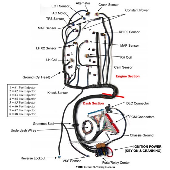
Schematic representation is a critical component of a 5.3 Vortec Engine Wiring Harness Diagram, providing a visual representation of the electrical connections within the engine. It serves as a roadmap for technicians, enabling them to trace the flow of electricity and identify potential issues. Without a schematic representation, troubleshooting electrical problems would be significantly more challenging and time-consuming.
Real-life examples of schematic representation in a 5.3 Vortec Engine Wiring Harness Diagram include:
- The main power distribution circuit, showing the connection between the battery, starter, alternator, and fuse box.
- The ignition system circuit, detailing the connections between the ignition coil, spark plugs, and electronic control module (ECM).
- The fuel injection system circuit, illustrating the connections between the fuel injectors, fuel pump, and ECM.
Understanding the schematic representation of a 5.3 Vortec Engine Wiring Harness Diagram is essential for various practical applications, including:
- Troubleshooting electrical problems, such as shorts, open circuits, or faulty components.
- Installing or replacing electrical components, ensuring proper connections and functionality.
- Modifying the electrical system to enhance engine performance or add accessories.
Electrical Connections
Electrical Connections are the backbone of a 5.3 Vortec Engine Wiring Harness Diagram, representing the intricate web of wires, connectors, and terminals that transmit electrical signals and power throughout the engine. Understanding these connections is crucial for diagnosing and repairing electrical issues, as well as for modifying or customizing the engine’s electrical system.
-
Main Power Distribution
Connects the battery to the starter, alternator, and fuse box, distributing electrical power throughout the engine. -
Ignition System
Links the ignition coil, spark plugs, and electronic control module (ECM), controlling the timing and delivery of spark to the engine’s cylinders. -
Fuel Injection System
Connects the fuel injectors, fuel pump, and ECM, regulating the delivery of fuel to the engine’s cylinders. -
Sensor and Actuator Circuits
Transmit signals between various sensors (e.g., oxygen sensors, temperature sensors) and actuators (e.g., fuel injectors, solenoids) to optimize engine performance and emissions.
Each of these electrical connections is critical to the proper functioning of the 5.3 Vortec engine. A thorough understanding of these connections is essential for technicians and enthusiasts alike, ensuring the reliable operation and optimal performance of the engine.
Diagnostic Tool
Within the context of a 5.3 Vortec Engine Wiring Harness Diagram, a diagnostic tool plays a vital role in troubleshooting electrical issues and ensuring the proper functioning of the engine. By utilizing a diagnostic tool, technicians and enthusiasts can identify and resolve electrical problems quickly and efficiently, minimizing downtime and maximizing engine performance.
A diagnostic tool, often referred to as a scan tool or code reader, interfaces with the engine’s electronic control module (ECM) through the vehicle’s diagnostic port. This allows the tool to access and interpret data from the ECM, including trouble codes, sensor readings, and actuator statuses. By analyzing this data, technicians can pinpoint the source of electrical issues, whether it’s a faulty sensor, a loose connection, or a more complex problem.
Real-life examples of diagnostic tools being used in conjunction with 5.3 Vortec Engine Wiring Harness Diagrams include:
- Identifying a faulty oxygen sensor by monitoring its voltage output and comparing it to the manufacturer’s specifications.
- Diagnosing a short circuit in the ignition system by measuring resistance and continuity along the wiring harness.
- Troubleshooting a malfunctioning fuel injector by observing its pulse width and comparing it to the desired value.
Understanding the connection between diagnostic tools and 5.3 Vortec Engine Wiring Harness Diagrams is crucial for effective engine diagnostics and repairs. By leveraging the capabilities of diagnostic tools, technicians can quickly and accurately identify electrical issues, saving time and ensuring the optimal performance of the engine.
Repair Guide
Within the context of “5.3 Vortec Engine Wiring Harness Diagram”, the aspect of “Repair Guide” holds immense significance. It serves as a valuable tool in the hands of technicians and enthusiasts, providing essential guidance for diagnosing and repairing electrical issues within the engine’s wiring harness.
-
Component Identification
The repair guide provides detailed diagrams and descriptions, enabling users to accurately identify the various components of the wiring harness, including sensors, actuators, connectors, and terminals.
-
Circuit Troubleshooting
With the aid of the repair guide, technicians can systematically troubleshoot electrical circuits, tracing the flow of current and testing components to locate faults and identify the root cause of electrical problems.
-
Repair Instructions
The guide offers step-by-step instructions for repairing or replacing damaged components within the wiring harness, including procedures for soldering, crimping, and splicing wires.
-
Real-life Examples
The repair guide often includes real-life examples of common electrical issues and their corresponding solutions, providing valuable insights for practical troubleshooting and repairs.
By delving into the multifaceted aspects of “Repair Guide” in relation to “5.3 Vortec Engine Wiring Harness Diagram”, we gain a comprehensive understanding of its critical role in maintaining and servicing vehicles equipped with this engine. The insights gleaned from this exploration empower technicians and enthusiasts alike to effectively diagnose and repair electrical issues, ensuring optimal engine performance and reliability.
Engine Performance
Within the realm of “5.3 Vortec Engine Wiring Harness Diagram”, “Engine Performance” emerges as a pivotal aspect, directly tied to the efficient operation and optimal output of the engine. The intricate web of electrical connections, as depicted in the wiring harness diagram, plays a fundamental role in orchestrating various components and systems, ultimately shaping the overall performance of the engine.
-
Fuel Delivery
The wiring harness ensures precise control over fuel delivery, regulating the flow of fuel to the engine’s cylinders. By coordinating with sensors and actuators, it optimizes fuel injection timing and quantity, leading to efficient combustion and enhanced power output.
-
Ignition Timing
The wiring harness precisely manages ignition timing, determining the optimal moment for spark delivery to the cylinders. This critical function ensures complete combustion, maximizing engine efficiency and minimizing harmful emissions.
-
Emission Control
The wiring harness integrates with emission control systems, monitoring and regulating various parameters. By controlling sensors and actuators, it ensures compliance with emission standards while optimizing engine performance.
-
Diagnostics and Monitoring
The wiring harness facilitates comprehensive engine diagnostics and monitoring. Through sensors and actuators, it collects vital data on engine operation, enabling early detection of potential issues and proactive maintenance, preventing costly breakdowns and ensuring reliable performance.
In conclusion, the “5.3 Vortec Engine Wiring Harness Diagram” serves as a crucial guide for understanding and optimizing “Engine Performance”. By deciphering the intricate electrical connections, technicians and enthusiasts can pinpoint potential issues, fine-tune engine parameters, and maximize the efficiency, power, and reliability of the engine.
Customization Potential
Within the realm of “5.3 Vortec Engine Wiring Harness Diagram”, “Customization Potential” emerges as a significant aspect, offering unparalleled opportunities to tailor and enhance the engine’s performance and functionality.
-
Performance Optimization
The wiring harness diagram empowers users to modify and fine-tune various engine parameters, such as fuel injection timing, ignition timing, and air/fuel ratio. This customization potential allows for increased power output, improved fuel efficiency, and optimized performance under specific driving conditions.
-
Accessory Integration
The wiring harness provides flexibility for integrating additional accessories and components into the engine system. This may include aftermarket gauges, performance chips, or specialized sensors, enabling users to enhance the engine’s functionality and monitoring capabilities.
-
Diagnostic Enhancement
Through strategic modifications to the wiring harness, users can expand the engine’s diagnostic capabilities. This may involve adding custom sensors or modifying existing ones, allowing for more comprehensive monitoring and troubleshooting of engine performance.
-
Compatibility Considerations
The customization potential of the “5.3 Vortec Engine Wiring Harness Diagram” must be carefully evaluated in conjunction with the vehicle’s overall electrical system. Modifications should be compatible with the vehicle’s existing wiring and electronic components to ensure proper functionality and prevent potential issues.
In conclusion, the “Customization Potential” of “5.3 Vortec Engine Wiring Harness Diagram” unleashes a world of possibilities for engine enthusiasts and performance seekers. By leveraging the diagram’s insights, users can unlock the engine’s true potential, enhance its functionality, and tailor it to their specific needs, resulting in an unparalleled driving experience.
Safety and Reliability
Within the context of “5.3 Vortec Engine Wiring Harness Diagram”, “Safety and Reliability” emerge as paramount considerations, underpinning the integrity and dependable operation of the engine. The wiring harness diagram serves as a critical guide in ensuring electrical safety, preventing malfunctions, and maintaining optimal engine performance.
-
Proper Grounding
The wiring harness diagram ensures proper grounding of electrical components, creating a safe path for current flow and preventing electrical hazards. Inadequate grounding can lead to electrical shorts, component damage, and even fire.
-
Circuit Protection
The diagram incorporates circuit protection measures, such as fuses and relays, to safeguard electrical components from overloads and short circuits. These protective devices prevent damage to sensitive electronics and prevent electrical fires.
-
Durability and Robustness
The wiring harness is designed to withstand harsh operating conditions, including vibrations, extreme temperatures, and exposure to fluids. Robust construction materials and proper insulation ensure reliable electrical connections and prevent premature failure.
-
Diagnostic Capabilities
The wiring harness diagram facilitates comprehensive engine diagnostics, allowing technicians to quickly identify and troubleshoot electrical issues. This enhances safety by preventing minor problems from escalating into major failures.
In conclusion, the “5.3 Vortec Engine Wiring Harness Diagram” plays a vital role in ensuring “Safety and Reliability” by promoting proper grounding, incorporating circuit protection measures, utilizing durable construction, and providing diagnostic capabilities. Understanding and adhering to the guidelines outlined in the diagram is essential for maintaining a safe and reliable engine operation, preventing costly repairs, and ensuring peace of mind for vehicle owners.
Compatibility and Standardization
Within the context of “5.3 Vortec Engine Wiring Harness Diagram”, “Compatibility and Standardization” emerge as vital considerations, ensuring seamless integration, reliable operation, and adherence to industry best practices.
-
Interchangeable Components
The diagram ensures compatibility between the wiring harness and various engine components, allowing for easy replacement and interchangeability of parts. This simplifies repairs, reduces downtime, and ensures a consistent level of performance.
-
OEM Standards Compliance
The wiring harness diagram adheres to OE (Original Equipment) standards, guaranteeing compatibility with the vehicle’s factory-installed electrical system. This compliance ensures proper functionality, prevents electrical issues, and maintains the integrity of the engine’s performance.
-
Industry Best Practices
The diagram incorporates industry-recognized best practices for electrical system design, ensuring reliability, safety, and ease of maintenance. This adherence to standards promotes efficient troubleshooting, minimizes potential hazards, and extends the lifespan of the wiring harness.
-
Real-Life Examples
Compatibility and standardization enable seamless integration of accessories and upgrades, such as performance chips, diagnostic tools, and aftermarket components. This flexibility allows for customization and enhancement of the engine’s functionality to meet specific requirements.
In summary, “Compatibility and Standardization” play a crucial role in the “5.3 Vortec Engine Wiring Harness Diagram”, ensuring the harmonious operation of the electrical system, facilitating efficient maintenance, and promoting adherence to industry best practices. By understanding and following the guidelines outlined in the diagram, technicians and enthusiasts can maintain optimal engine performance, prevent costly repairs, and ensure the reliable operation of their vehicles.
Technical Documentation
Within the realm of “5.3 Vortec Engine Wiring Harness Diagram”, “Technical Documentation” emerges as a cornerstone of accurate and comprehensive information, providing a structured framework for understanding and servicing the electrical system of the engine. This documentation serves as an indispensable guide, empowering technicians and enthusiasts alike to navigate the complexities of the wiring harness and its intricate connections.
-
Schematic Diagrams
Technical documentation includes detailed schematic diagrams that visually represent the electrical connections within the wiring harness. These diagrams provide a comprehensive overview of the system’s architecture, enabling users to trace the flow of electricity and identify specific components.
-
Component Specifications
The documentation also encompasses detailed specifications for each component within the wiring harness. This information includes electrical ratings, pinouts, and compatibility data, ensuring that replacement parts are properly matched to the original system.
-
Diagnostic Procedures
Technical documentation often includes step-by-step diagnostic procedures for troubleshooting electrical issues within the wiring harness. These procedures guide users through a series of tests and measurements, helping to pinpoint the source of electrical faults.
-
Maintenance Schedules
The documentation may also provide recommended maintenance schedules for the wiring harness, outlining periodic inspections and cleaning procedures to ensure optimal performance and longevity.
In conclusion, “Technical Documentation” plays a vital role in the context of “5.3 Vortec Engine Wiring Harness Diagram” by providing a comprehensive repository of information essential for understanding, troubleshooting, and maintaining the electrical system of the engine. These documents empower technicians and enthusiasts to confidently diagnose and repair electrical issues, ensuring the reliable operation and optimal performance of the engine.
Industry Standards
Within the realm of “5.3 Vortec Engine Wiring Harness Diagram”, “Industry Standards” emerge as a critical component, shaping the design, implementation, and maintenance of the electrical system. These standards establish a common set of guidelines and best practices that ensure compatibility, safety, and reliability across different manufacturers and applications.
The adherence to industry standards is paramount in the development of 5.3 Vortec engine wiring harness diagrams. By conforming to established norms, manufacturers can guarantee that their products meet specific performance and safety requirements. This standardization enables the interchangeability of components, simplifies troubleshooting procedures, and facilitates the exchange of knowledge and expertise among technicians.
Real-life examples of industry standards within 5.3 Vortec engine wiring harness diagrams include the use of color-coded wires to denote specific functions, the adoption of standardized connectors to ensure proper mating, and the incorporation of protective measures such as fuses and circuit breakers to prevent electrical hazards. These standards ensure that technicians can quickly identify and diagnose issues, reducing downtime and improving overall system reliability.
Understanding the connection between industry standards and 5.3 Vortec engine wiring harness diagrams has practical applications in various domains. For manufacturers, it enables the production of high-quality, reliable wiring harnesses that meet customer expectations and regulatory requirements. For technicians, it provides a framework for efficient troubleshooting and repair, reducing maintenance costs and ensuring optimal engine performance. For vehicle owners, it guarantees safety, reliability, and peace of mind, knowing that their engine’s electrical system adheres to established industry standards.

![[DIAGRAM] Vortec Engine Wiring Harness Diagram](https://i0.wp.com/arts.bmwofstratham.com/images/parts/BMW/fullsize/206174.jpg?w=665&ssl=1)


Related Posts


