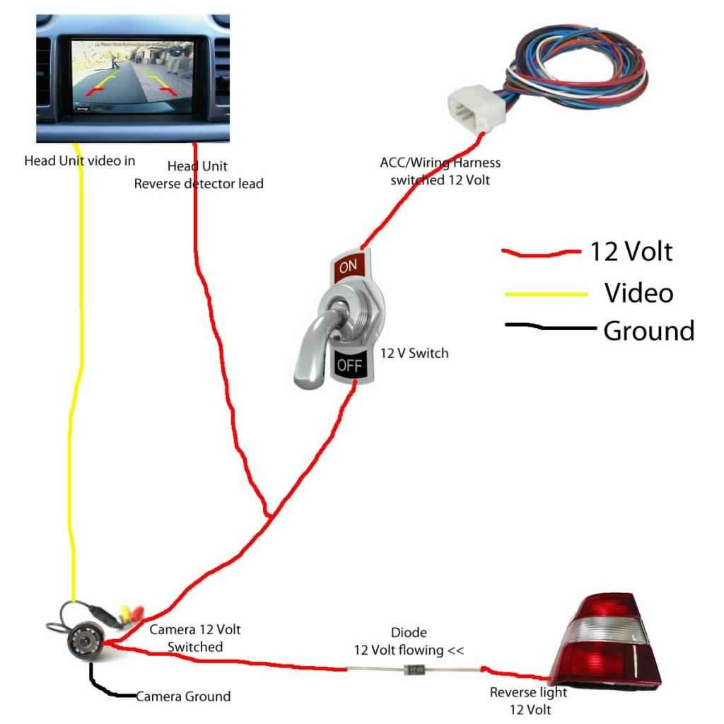
A 5 Wire Reverse Camera Wiring Diagram outlines the electrical connections required to install a reverse camera system. It typically includes wires for the camera’s power, ground, video signal, and a trigger wire that activates the camera when the vehicle is in reverse.
Diagrams such as these help with the installation of reverse cameras, which enhance visibility for drivers while reversing. They provide the necessary information for connecting the camera to the vehicle’s electrical system, ensuring proper functionality and safety. Furthermore, they contribute to the broader field of automotive safety technology.
With the increasing complexity of vehicle electrical systems, wiring diagrams have become essential tools for technicians and DIY enthusiasts alike. Understanding these diagrams enables efficient and reliable installation of essential equipment, helping to keep vehicles and their drivers safe.
5 Wire Reverse Camera Wiring Diagrams play a vital role in the installation and functionality of reverse camera systems. Understanding the key aspects of these diagrams is crucial for proper installation and maintenance.
- Wiring Configuration: The diagram specifies the connections between the camera, monitor, and vehicle’s electrical system.
- Power Supply: It indicates the power requirements for the camera and how to connect it to the vehicle’s power source.
- Grounding: Proper grounding ensures a stable electrical connection and prevents electrical interference.
- Video Signal Transmission: The diagram outlines the type of video signal transmitted from the camera to the monitor.
- Trigger Wire: This wire activates the camera when the vehicle is in reverse, providing a clear view behind the vehicle.
- Compatibility: The diagram ensures compatibility between the camera, monitor, and vehicle’s electrical system.
- Safety Features: Some diagrams include instructions for integrating safety features, such as automatic obstacle detection.
- Troubleshooting: The diagram can assist in diagnosing and resolving any issues with the camera system.
- Customization Options: Advanced diagrams may provide options for customizing the camera’s settings and functionality.
- Installation Instructions: The diagram often includes step-by-step instructions for installing the camera system.
These key aspects of 5 Wire Reverse Camera Wiring Diagrams contribute to the safe and effective operation of reverse camera systems. Proper understanding and implementation of these diagrams ensure clear visibility, enhanced safety, and a seamless user experience.
Wiring Configuration
Within a 5 Wire Reverse Camera Wiring Diagram, wiring configuration plays a crucial role in establishing proper connections between the camera, monitor, and vehicle’s electrical system. This configuration ensures the camera receives power, transmits video signals, and activates when the vehicle is in reverse.
Without a clear understanding of wiring configuration, the camera system may not function correctly, leading to poor visibility and potential safety hazards. The diagram provides detailed instructions on connecting each wire to its designated terminal, ensuring a stable and reliable electrical connection.
For instance, the power wire must be connected to a constant power source, while the ground wire must be connected to a suitable grounding point on the vehicle’s chassis. The video signal wire transmits the camera’s video feed to the monitor, and the trigger wire activates the camera when the vehicle is shifted into reverse.
By following the wiring configuration specified in the diagram, installers can ensure that the reverse camera system operates as intended, providing clear visibility and enhanced safety for drivers.
Power Supply
In the context of a 5 Wire Reverse Camera Wiring Diagram, understanding the power supply aspect is paramount. It ensures the camera receives the necessary electrical power to function correctly, providing clear visibility for drivers when reversing. This section explores crucial facets of power supply in relation to the diagram.
- Voltage Requirements: The diagram specifies the voltage requirements of the camera, typically 12V or 24V. This information guides the selection of an appropriate power source within the vehicle.
- Power Source Identification: The diagram indicates suitable power sources within the vehicle’s electrical system, such as the reverse light circuit or a dedicated power outlet.
- Wiring Specifications: The diagram provides details on the wire gauge and length required for the power connection, ensuring sufficient current flow and minimizing voltage drop.
- Grounding: Proper grounding is crucial for stable electrical operation. The diagram specifies the grounding point on the vehicle’s chassis, ensuring a secure electrical connection.
By addressing these facets of power supply, the 5 Wire Reverse Camera Wiring Diagram empowers installers to establish a reliable and efficient electrical connection for the camera. This ensures the camera receives the necessary power to operate effectively, enhancing safety and visibility for drivers during reversing maneuvers.
Grounding
Within the context of a 5 Wire Reverse Camera Wiring Diagram, grounding plays a critical role in ensuring the stable and reliable operation of the camera system. Proper grounding provides a reference point for electrical current, preventing voltage fluctuations and ensuring a clear and stable video signal.
Electrical interference, often caused by electromagnetic fields or ground loops, can disrupt the camera’s operation, resulting in distorted or unreliable images. Proper grounding minimizes these effects by providing a low-resistance path for electrical current to flow, preventing it from interfering with the camera’s video signal.
In a 5 Wire Reverse Camera Wiring Diagram, the grounding wire is typically connected to the vehicle’s chassis or a dedicated grounding point. This connection establishes a solid electrical connection between the camera and the vehicle’s electrical system, ensuring a stable reference point for electrical current.
Real-life examples of proper grounding in a 5 Wire Reverse Camera Wiring Diagram include:
- Connecting the grounding wire to a bare metal surface on the vehicle’s chassis.
- Using a dedicated grounding point provided by the vehicle manufacturer.
- Ensuring that the grounding wire is properly sized and securely connected.
Understanding the importance of grounding in a 5 Wire Reverse Camera Wiring Diagram enables installers to create a reliable and interference-free camera system. This, in turn, enhances the safety and convenience of reversing maneuvers, providing drivers with a clear view behind their vehicle.
Video Signal Transmission
Within the context of a 5 Wire Reverse Camera Wiring Diagram, understanding video signal transmission is crucial for ensuring a clear and stable display on the monitor. The diagram specifies the type of video signal used, whether analog or digital, and provides guidance on the necessary connections and components.
- Signal Type: The diagram indicates the type of video signal used, typically analog (CVBS) or digital (AHD, TVI, or CVI). This determines the compatibility between the camera and monitor.
- Video Connector: The diagram specifies the video connector type, such as RCA or BNC, which are commonly used for analog and digital signals respectively.
- Cable Selection: The diagram provides recommendations for the type of video cable to use, considering factors like signal type, cable length, and image quality.
- Signal Interference: The diagram may include measures to minimize signal interference, such as proper grounding and shielding, ensuring a clear and stable video transmission.
Understanding video signal transmission in a 5 Wire Reverse Camera Wiring Diagram is essential for installers to establish a reliable connection between the camera and monitor. This ensures that drivers have a clear view behind their vehicle when reversing, enhancing safety and reducing the risk of accidents.
Trigger Wire
Within the context of a 5 Wire Reverse Camera Wiring Diagram, understanding the trigger wire is essential for ensuring the camera activates when the vehicle is in reverse, providing drivers with a clear view behind their vehicle. This wire plays a crucial role in the overall functionality of the reverse camera system, enabling safe and convenient reversing maneuvers.
- Activation Mechanism: The trigger wire is connected to the vehicle’s reverse light circuit. When the vehicle is shifted into reverse, power flows through the trigger wire, activating the reverse camera.
- Compatibility: The trigger wire is typically compatible with both analog and digital reverse camera systems, ensuring versatility in system design.
- Safety Implications: The trigger wire ensures that the reverse camera only activates when the vehicle is in reverse, preventing unnecessary distraction to the driver and enhancing safety.
- Customization Options: In some advanced reverse camera systems, the trigger wire can be customized to activate additional features, such as automatic obstacle detection or lane departure warnings.
By understanding the trigger wire and its role within the 5 Wire Reverse Camera Wiring Diagram, installers can create a reliable and effective reverse camera system. This contributes to enhanced safety, convenience, and peace of mind for drivers when reversing their vehicles.
Compatibility
Within the context of a 5 Wire Reverse Camera Wiring Diagram, compatibility plays a crucial role in ensuring that the camera, monitor, and vehicle’s electrical system work seamlessly together. The diagram provides essential information to achieve compatibility, enabling the reverse camera system to operate effectively and reliably.
- Signal Formats: The diagram ensures compatibility between the camera’s video output format and the monitor’s input format. This includes analog (CVBS) or digital (AHD, TVI, CVI) formats, ensuring a clear and stable video display.
- Power Requirements: The diagram specifies the camera’s power requirements and ensures compatibility with the vehicle’s electrical system. This includes voltage and current compatibility, preventing damage to the camera or electrical system.
- Trigger Mechanisms: The diagram ensures compatibility between the camera’s trigger mechanism and the vehicle’s reverse gear signal. This ensures that the camera activates only when the vehicle is in reverse, providing a clear view behind the vehicle.
- Wiring Standards: The diagram adheres to established wiring standards and color codes, ensuring compatibility with industry-standard components. This simplifies the installation process and reduces the risk of wiring errors.
By addressing compatibility within the 5 Wire Reverse Camera Wiring Diagram, installers can create a reliable and effective reverse camera system. This enhances safety and convenience for drivers, providing them with a clear view behind their vehicle during reversing maneuvers.
Safety Features
Within the context of a 5 Wire Reverse Camera Wiring Diagram, safety features play a crucial role in enhancing the safety and convenience of reversing maneuvers. These diagrams often include instructions for integrating safety features, such as automatic obstacle detection, to provide drivers with additional assistance and peace of mind.
Automatic obstacle detection is a valuable safety feature that utilizes sensors and algorithms to detect obstacles behind the vehicle. When the vehicle is in reverse, the system activates and provides visual or audible alerts to the driver, warning them of potential hazards. This feature is particularly useful in low-visibility conditions or when reversing in tight spaces.
The integration of safety features into a 5 Wire Reverse Camera Wiring Diagram requires careful consideration of the following aspects:
- Sensor Compatibility: The diagram ensures compatibility between the reverse camera and the sensors used for obstacle detection.
- Wiring Configuration: The diagram provides detailed instructions on how to connect the sensors and other components to the camera and vehicle’s electrical system.
- Display Integration: The diagram specifies how the obstacle detection information is displayed to the driver, whether through the reverse camera monitor or a dedicated display.
By understanding the connection between safety features and 5 Wire Reverse Camera Wiring Diagrams, installers can create a comprehensive reverse camera system that enhances both visibility and safety. This contributes to a more informed driving experience, reducing the risk of accidents and increasing peace of mind for drivers.
Troubleshooting
Within the context of a 5 Wire Reverse Camera Wiring Diagram, troubleshooting plays a vital role in maintaining a functional and reliable reverse camera system. The diagram provides valuable guidance for diagnosing and resolving any issues that may arise, ensuring optimal performance and safety.
- Identifying Electrical Faults: The diagram helps identify electrical faults by providing a clear layout of the wiring connections. This enables technicians to systematically check for loose connections, shorts, or breaks in the wires, ensuring proper electrical flow.
- Camera Malfunction Diagnosis: The diagram aids in diagnosing camera malfunctions by indicating the correct voltage and polarity requirements for the camera. By verifying these parameters, technicians can determine if the camera is receiving the necessary power and is functioning properly.
- Signal Transmission Issues: The diagram assists in troubleshooting signal transmission issues by specifying the type of video signal used and the recommended cable type. This information helps ensure that the video signal is being transmitted correctly from the camera to the monitor, eliminating potential signal degradation or loss.
- Integration Problems: The diagram can help resolve integration problems by providing compatibility information. It ensures that the reverse camera is compatible with the vehicle’s electrical system, preventing issues with power supply, triggering, or video display.
By utilizing the troubleshooting guidance provided in a 5 Wire Reverse Camera Wiring Diagram, technicians can efficiently diagnose and resolve any issues with the camera system. This contributes to a reliable and effective reverse camera system, enhancing safety and convenience for drivers.
Customization Options
Within the context of a 5 Wire Reverse Camera Wiring Diagram, customization options play a significant role in tailoring the camera’s settings and functionality to specific user preferences and vehicle requirements.
Advanced diagrams often provide instructions and specifications for customizing camera settings, including:
- Adjusting image brightness, contrast, and sharpness to optimize visibility under varying lighting conditions.
- Modifying camera viewing angles to suit different vehicle types and mounting positions.
- Enabling or disabling features such as parking guidelines, mirror imaging, and motion detection.
These customization options empower users to optimize the camera’s performance and functionality, enhancing the overall driving experience. For instance, adjusting the camera’s viewing angle can provide a wider field of view when reversing in tight spaces or towing a trailer.
Understanding the customization options provided in a 5 Wire Reverse Camera Wiring Diagram empowers users to tailor the camera’s settings to their specific needs, resulting in a more personalized and effective reverse camera system.
Installation Instructions
Within the context of a 5 Wire Reverse Camera Wiring Diagram, installation instructions play a crucial role in guiding users through the process of setting up the camera system. These instructions provide a clear and systematic approach to ensure proper installation, ensuring optimal performance and safety.
Real-life examples of installation instructions within a 5 Wire Reverse Camera Wiring Diagram include:
- Detailed descriptions of the necessary tools and materials for the installation.
- Step-by-step instructions for mounting the camera and connecting the wiring.
- Calibration procedures to ensure accurate image display.
Understanding the installation instructions provided in a 5 Wire Reverse Camera Wiring Diagram empowers users to confidently and effectively install the camera system. This not only ensures proper functionality but also contributes to the overall safety and convenience of the vehicle.
In summary, installation instructions are an integral part of 5 Wire Reverse Camera Wiring Diagrams, providing users with the necessary guidance to set up the camera system correctly. Understanding these instructions is essential for a successful installation, enhancing the driving experience and promoting safety on the road.


Related Posts


