A 5 pin trailer wiring diagram with brakes is a blueprint that outlines the electrical connections between a tow vehicle and a trailer equipped with a braking system. It specifies the pin configuration, wire colors, and functions for each wire, ensuring proper communication and operation of the trailer’s brake lights, turn signals, and running lights.
The wiring diagram is crucial for safe towing, as it establishes the electrical pathway for the trailer to respond to the tow vehicle’s braking and signaling inputs. Without a properly wired connection, the trailer’s lights and brakes may malfunction, posing safety hazards to the drivers and other road users.
A 5 pin trailer wiring diagram with brakes has gained widespread adoption in the transportation industry due to its simplicity, reliability, and standardization. It enables seamless electrical integration between different tow vehicles and trailers, regardless of their makes or models. This standardization has simplified the installation and maintenance of trailer wiring systems, enhancing the overall safety and efficiency of towing operations.
The various aspects of a 5 Pin Trailer Wiring Diagram with Brakes are essential for understanding its functionality and safe application. Each aspect plays a crucial role in ensuring proper electrical communication between the tow vehicle and the trailer, facilitating the operation of the trailer’s lighting and braking systems. Here are 8 key aspects to consider:
- Pin Configuration: The physical arrangement of the 5 pins on the connector determines the functions of each wire.
- Wire Colors: Standardized wire colors ensure consistent connections and easy identification during installation and troubleshooting.
- Grounding: A proper grounding connection provides a safe and stable electrical path for the system.
- Brake Light Circuit: This circuit controls the operation of the trailer’s brake lights.
- Turn Signal Circuit: This circuit enables the trailer’s turn signals to function.
- Running Light Circuit: This circuit powers the trailer’s running lights, making it visible to other road users.
- Auxiliary Circuit: This circuit provides additional electrical power for other trailer functions, such as charging batteries or powering accessories.
- Compatibility: The wiring diagram must be compatible with both the tow vehicle and the trailer’s electrical systems.
These aspects are interconnected and interdependent, forming a complete electrical system that ensures the safe and effective operation of the trailer. Understanding these aspects is crucial for proper installation, maintenance, and troubleshooting of 5 Pin Trailer Wiring Diagrams with Brakes.
Pin Configuration
In the context of “5 Pin Trailer Wiring Diagram with Brakes”, the pin configuration refers to the specific arrangement of the 5 pins on the electrical connector that physically connects the tow vehicle to the trailer. This configuration determines the function of each wire, ensuring proper communication and operation of the trailer’s lighting and braking systems.
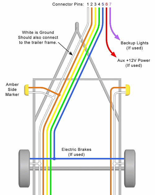
- Pin 1: Ground: Provides a grounding connection for the entire system, ensuring a stable electrical path.
- Pin 2: Left Turn Signal: Controls the operation of the left turn signal on the trailer.
- Pin 3: Brake Lights: Powers the trailer’s brake lights, indicating when the brakes are applied.
- Pin 4: Right Turn Signal: Controls the operation of the right turn signal on the trailer.
- Pin 5: Running Lights: Provides power to the trailer’s running lights, making it visible to other road users.
Understanding the pin configuration is essential for proper installation and maintenance of the trailer wiring system. Incorrect pin connections can lead to malfunctioning lights or brakes, posing safety hazards. The standardized pin configuration ensures compatibility between different tow vehicles and trailers, simplifying the wiring process and enhancing overall safety and efficiency in towing operations.
Wire Colors
In the context of “5 Pin Trailer Wiring Diagram With Brakes”, standardized wire colors play an essential role in ensuring proper electrical connections and facilitating efficient troubleshooting. The use of consistent color coding for each wire’s function simplifies the installation process and allows for quick identification during maintenance or repairs.
- Color-Coded Wires: Each wire in the 5 pin trailer wiring diagram is assigned a specific color, such as yellow for left turn signal, green for right turn signal, and red for brake lights. This color coding helps in easily identifying the correct wire for each connection, minimizing the risk of incorrect wiring.
- Simplified Installation: Standardized wire colors make it easier for installers to follow the wiring diagram and connect the wires accordingly. This reduces the chances of errors during installation, ensuring the proper functioning of the trailer’s lighting and braking systems.
- Easy Troubleshooting: In case of any electrical issues, the color-coded wires aid in quick and accurate troubleshooting. By tracing the wires based on their colors, technicians can easily locate the source of the problem, minimizing downtime and ensuring a safe and efficient repair.
- Universal Compatibility: Standardized wire colors promote universal compatibility between different tow vehicles and trailers. By adhering to the same color coding scheme, manufacturers ensure that trailers can be easily connected to various tow vehicles without the need for extensive rewiring or modifications.
Overall, standardized wire colors in 5 Pin Trailer Wiring Diagrams With Brakes enhance safety, simplify installation and maintenance, and promote universal compatibility. The consistent color coding helps in establishing reliable electrical connections, enabling the trailer’s lighting and braking systems to function properly and ensuring a secure towing experience.
Grounding
In the context of “5 Pin Trailer Wiring Diagram with Brakes”, grounding plays a critical role in ensuring the safe and reliable operation of the trailer’s electrical system. A proper grounding connection provides a stable electrical path, completing the circuit and allowing current to flow effectively. Without a proper ground, the electrical system can malfunction, leading to potential safety hazards.
- Chassis Ground: The trailer’s chassis serves as the primary grounding point, providing a direct connection to the earth. This connection ensures that any electrical faults or surges are safely discharged, preventing damage to the electrical components and minimizing the risk of electrical shock.
- Ground Wire: A dedicated ground wire is typically used to connect the trailer’s electrical system to the chassis ground. This wire provides a low-resistance path for current to flow, ensuring a stable ground connection.
- Electrical Components: All electrical components in the trailer’s lighting and braking system rely on a proper ground connection to function correctly. Headlights, taillights, turn signals, and brake lights require a complete circuit to operate, and grounding completes that circuit.
- Safety and Reliability: A proper grounding connection is essential for the safety and reliability of the trailer’s electrical system. It prevents electrical malfunctions, reduces the risk of electrical fires, and ensures that the trailer’s lights and brakes function as intended, enhancing overall towing safety.
In summary, grounding provides a safe and stable electrical path for the “5 Pin Trailer Wiring Diagram with Brakes”, ensuring the proper operation of the trailer’s lighting and braking systems. A well-grounded system minimizes electrical hazards, enhances reliability, and contributes to the overall safety of towing operations.
Brake Light Circuit
Within the context of “5 Pin Trailer Wiring Diagram With Brakes”, the brake light circuit holds critical importance in ensuring the safety and functionality of the trailer’s braking system. This circuit is responsible for transmitting electrical signals from the tow vehicle to the trailer’s brake lights, enabling them to illuminate when the brakes are applied. A well-functioning brake light circuit is vital for effective communication between the tow vehicle and the trailer, preventing rear-end collisions and ensuring the safety of all road users.
- Electrical Components: The brake light circuit comprises various electrical components, including the brake light switch, wiring harness, and brake light bulbs. These components work in unison to transmit electrical signals and illuminate the brake lights.
- Brake Light Switch: The brake light switch is a crucial component of the brake light circuit. When the driver applies pressure to the brake pedal, this switch activates, completing the circuit and sending a signal to the trailer’s brake lights.
- Wiring Harness: The wiring harness serves as the pathway for electrical signals to travel from the tow vehicle to the trailer’s brake lights. It consists of color-coded wires that are connected according to the “5 Pin Trailer Wiring Diagram With Brakes”.
- Brake Light Bulbs: The brake light bulbs are the final components in the brake light circuit. When electrical current flows through the circuit, these bulbs illuminate, signaling to following vehicles that the trailer is braking.
In summary, the brake light circuit in a “5 Pin Trailer Wiring Diagram With Brakes” plays a pivotal role in ensuring the safe operation of the trailer’s braking system. Proper installation and maintenance of this circuit are paramount for effective communication between the tow vehicle and the trailer, enhancing overall towing safety and preventing accidents.
Turn Signal Circuit
Within the comprehensive framework of “5 Pin Trailer Wiring Diagram With Brakes”, the turn signal circuit assumes a critical role in ensuring effective communication between the tow vehicle and the trailer during turning maneuvers. This circuit allows the driver’s intentions to be relayed to other road users, preventing accidents and enhancing overall safety on the road.
- Electrical Components: The turn signal circuit comprises various electrical components, including the turn signal switch, flasher relay, wiring harness, and turn signal bulbs. These components work in unison to transmit electrical signals and illuminate the turn signals.
- Turn Signal Switch: The turn signal switch is a pivotal component of the turn signal circuit. When the driver engages the turn signal lever, this switch activates, sending a signal to the flasher relay.
- Flasher Relay: The flasher relay regulates the blinking pattern of the turn signals. It receives the electrical signal from the turn signal switch and sends intermittent pulses of current to the turn signal bulbs, causing them to flash.
- Wiring Harness: The wiring harness serves as the pathway for electrical signals to travel from the tow vehicle to the trailer’s turn signals. It consists of color-coded wires that are connected according to the “5 Pin Trailer Wiring Diagram With Brakes”.
In summary, the turn signal circuit in a “5 Pin Trailer Wiring Diagram With Brakes” plays a crucial role in ensuring that the trailer’s turn signals function properly, enabling effective communication with other road users. Proper installation and maintenance of this circuit are essential for safe and compliant towing operations.
Running Light Circuit
Within the intricate framework of “5 Pin Trailer Wiring Diagram With Brakes”, the running light circuit assumes a fundamental role in ensuring the visibility and safety of the trailer during operation. This circuit is responsible for powering the trailer’s running lights, which serve as critical indicators of the trailer’s presence on the road, particularly during low-light conditions or inclement weather.
The running light circuit comprises various electrical components, including the light switch, wiring harness, and running light bulbs. When the light switch is activated, electrical current flows through the circuit, illuminating the running lights. The wiring harness serves as the pathway for electrical signals to travel from the tow vehicle to the trailer’s running lights. The running light bulbs, typically incandescent or LED, convert electrical energy into light, making the trailer visible to other road users.
The integration of the running light circuit within the “5 Pin Trailer Wiring Diagram With Brakes” is of paramount importance. Without functioning running lights, the trailer becomes virtually invisible to other vehicles, increasing the risk of accidents. Proper installation and maintenance of the running light circuit are therefore essential to ensure the safety and legality of towing operations.
In summary, the running light circuit in a “5 Pin Trailer Wiring Diagram With Brakes” plays a crucial role in enhancing the visibility of the trailer, preventing accidents, and promoting overall road safety. Understanding the connection between the running light circuit and the 5 Pin Trailer Wiring Diagram provides valuable insights into the importance of proper electrical connections for safe and compliant towing practices.
Auxiliary Circuit
Within the context of “5 Pin Trailer Wiring Diagram With Brakes”, the auxiliary circuit plays a crucial role in extending the electrical capabilities of the trailer beyond its basic lighting and braking functions. It provides an additional source of electrical power that can be utilized to operate various accessories or charge batteries, enhancing the overall functionality and convenience of the trailer.
The auxiliary circuit is typically connected to the tow vehicle’s electrical system via the 5-pin connector. This connection allows the trailer to draw power from the tow vehicle’s battery, enabling the operation of devices such as refrigerators, air conditioners, or battery chargers. The circuit is designed to handle higher electrical loads than the other circuits within the 5 Pin Trailer Wiring Diagram, ensuring that the connected devices receive adequate power.
Real-life examples of the auxiliary circuit in action include powering a small refrigerator in a camper trailer to keep food and beverages cold during a camping trip, or utilizing a battery charger to maintain the charge of the trailer’s battery while it is disconnected from the tow vehicle. Additionally, the auxiliary circuit can be used to power lighting systems, water pumps, or other accessories that enhance the comfort and convenience of the trailer.
Understanding the connection between the auxiliary circuit and the “5 Pin Trailer Wiring Diagram With Brakes” is essential for properly installing and utilizing electrical accessories in a trailer. By providing additional electrical power, the auxiliary circuit allows trailer owners to customize their trailers to meet their specific needs and enhance their overall towing experience.
Compatibility
Within the context of “5 Pin Trailer Wiring Diagram With Brakes”, compatibility plays a pivotal role in ensuring the seamless communication and operation between the tow vehicle and the trailer. The wiring diagram must be compatible with both the electrical systems of the tow vehicle and the trailer to establish a functional connection and enable proper functioning of the trailer’s lighting and braking systems.
- Connector Type: The physical connector used to connect the tow vehicle and the trailer must be compatible in terms of size, shape, and pin configuration. This ensures a secure and reliable electrical connection between the two vehicles.
- Voltage and Amperage: The electrical systems of the tow vehicle and the trailer must be compatible in terms of voltage and amperage. Mismatched voltage or amperage can damage electrical components or lead to malfunctions.
- Wiring Harness: The wiring harness used to connect the tow vehicle and the trailer must be compatible with both vehicles. This includes the length, gauge, and type of wiring used, as well as the pinouts (wire assignments) at each end of the harness.
- Grounding: The grounding systems of the tow vehicle and the trailer must be compatible to ensure a proper electrical path. This includes the location and type of grounding points, as well as the size and type of grounding wire used.
By ensuring compatibility between the tow vehicle and the trailer’s electrical systems, the “5 Pin Trailer Wiring Diagram With Brakes” facilitates the safe and reliable operation of the trailer. Proper compatibility ensures that the trailer’s lights and brakes function as intended, enhancing overall towing safety and preventing potential accidents.


Related Posts


