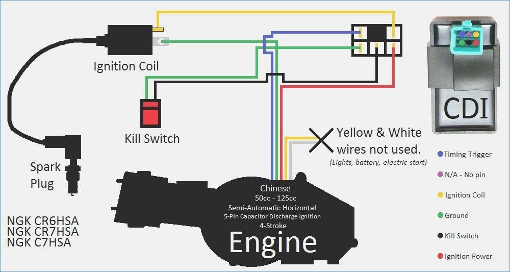
A 5-pin CDI wiring diagram color code is a standardized system used to identify the wires in a capacitive discharge ignition (CDI) system. Each wire in the system is assigned a specific color, which corresponds to a specific function. For example, the black wire is typically used for the ground, the red wire is typically used for the power, and the blue wire is typically used for the trigger. By following the color code, it is possible to quickly and easily identify the wires in a CDI system, which can be helpful for troubleshooting and repairs.
The 5-pin CDI wiring diagram color code is an important part of any CDI system. It ensures that the wires are connected correctly, which is essential for the proper operation of the system. The color code also makes it easier to troubleshoot and repair the system, as it can be used to quickly identify the wires that are causing problems.
The 5-pin CDI wiring diagram color code was developed in the early days of CDI systems, when there was a need for a standardized way to identify the wires in the system. The color code has been in use for many years, and it is now a well-established standard. It is used in a wide variety of CDI systems, including those used in motorcycles, snowmobiles, and ATVs.
The 5-pin CDI wiring diagram color code is a crucial aspect of capacitive discharge ignition (CDI) systems, providing a standardized method to identify and connect wires for optimal system performance. Understanding the key aspects of this color code is essential for effective troubleshooting, repairs, and system optimization. Here are nine key aspects to consider:
- Standardization: The color code ensures uniformity across CDI systems, facilitating easy identification and connection of wires.
- Function assignment: Each color represents a specific function within the CDI system, such as ground, power, and trigger.
- Wiring simplicity: By following the color code, technicians can quickly and accurately connect wires, reducing installation time and errors.
- Troubleshooting efficiency: The color code aids in troubleshooting by allowing technicians to swiftly identify faulty or disconnected wires.
- Repair accuracy: When repairs are necessary, the color code guides technicians in replacing wires with the correct function, ensuring system integrity.
- System optimization: Proper wire identification and connection using the color code optimizes CDI system performance and efficiency.
- Safety: Adhering to the color code minimizes the risk of incorrect connections, preventing potential electrical hazards.
- Industry acceptance: The 5-pin CDI wiring diagram color code is widely recognized and adopted within the industry, ensuring consistency across manufacturers.
- Historical significance: The color code has evolved over time to meet the needs of advancing CDI technology, ensuring compatibility and functionality.
These key aspects collectively highlight the importance of the 5-pin CDI wiring diagram color code in ensuring proper installation, maintenance, and optimization of CDI systems. By understanding and adhering to the color code, technicians can effectively manage CDI systems, contributing to improved performance, reliability, and safety.
Standardization
The standardization of the 5-pin CDI wiring diagram color code is a critical component of its effectiveness. By ensuring uniformity across CDI systems, it facilitates easy identification and connection of wires, regardless of the specific CDI system being used. This standardization streamlines the installation and maintenance processes, reducing errors and saving time.
For example, in a scenario where multiple technicians are working on different CDI systems, the standardized color code enables them to quickly and accurately connect the wires without the need for extensive documentation or cross-referencing. This uniformity also simplifies troubleshooting, as technicians can easily trace wires and identify potential issues based on their color coding.
The practical applications of this understanding extend beyond the initial installation and maintenance of CDI systems. The standardized color code allows for easy expansion or modification of systems, as new components can be integrated seamlessly by matching the wire colors. This flexibility is particularly beneficial in research and development settings, where experimental setups may require frequent reconfigurations.
In summary, the standardization of the 5-pin CDI wiring diagram color code is a crucial factor in its widespread adoption and ease of use. It ensures uniformity across CDI systems, facilitating easy identification and connection of wires, streamlining installation, maintenance, and troubleshooting processes. This standardization also enables flexible system expansion and modification, making it a valuable tool in both industrial and research environments.
Function assignment
Within the context of the 5-pin CDI wiring diagram color code, the function assignment aspect plays a critical role in ensuring the proper operation of the CDI system. Each color is assigned a specific function, such as ground, power, and trigger, which helps to simplify the installation, maintenance, and troubleshooting processes.
- Ground: The black wire is typically used for the ground connection. This wire provides a path for electrical current to flow back to the negative terminal of the battery, completing the circuit.
- Power: The red wire is typically used for the power connection. This wire provides electrical power from the battery to the CDI unit.
- Trigger: The blue wire is typically used for the trigger connection. This wire receives a signal from the ignition coil, which triggers the CDI unit to discharge energy to the spark plug.
By adhering to the function assignment aspect of the color code, technicians can ensure that the CDI system is wired correctly, which is essential for optimal performance and reliability. Incorrect wiring can lead to a variety of problems, such as engine misfires, poor performance, or even damage to the CDI unit itself.
Wiring simplicity
Within the context of the 5-pin CDI wiring diagram color code, the aspect of wiring simplicity holds significant importance. By adhering to the standardized color code, technicians can quickly and accurately connect wires, leading to reduced installation time and a decrease in the likelihood of errors.
The relationship between wiring simplicity and the 5-pin CDI wiring diagram color code is one of cause and effect. The color code provides a clear and consistent guide for technicians to follow, eliminating the need for complex memorization or referencing of documentation. This simplifies the wiring process, allowing technicians to complete installations and repairs more efficiently.
Real-life examples of wiring simplicity within the 5-pin CDI wiring diagram color code can be observed in various industries, including automotive, marine, and powersports. Technicians working on motorcycles, snowmobiles, and ATVs often rely on the color code to quickly identify and connect wires, ensuring proper functionality of the CDI system.
The practical applications of this understanding extend beyond the initial installation phase. The standardized color code enables easy troubleshooting and maintenance of CDI systems. By following the color code, technicians can quickly trace wires, identify potential issues, and make necessary repairs or adjustments.
In summary, the wiring simplicity aspect of the 5-pin CDI wiring diagram color code is a critical component that contributes to the overall effectiveness and ease of use of CDI systems. It reduces installation time, minimizes errors, and simplifies troubleshooting, leading to improved system performance and reliability.
Troubleshooting efficiency
Within the context of the 5-pin CDI wiring diagram color code, the aspect of troubleshooting efficiency plays a critical role in maintaining and repairing CDI systems. The color code aids technicians in swiftly identifying faulty or disconnected wires, enabling them to diagnose and resolve issues more quickly and accurately.
- Rapid wire identification: The color code allows technicians to quickly identify wires based on their function, such as ground, power, and trigger. This rapid identification simplifies troubleshooting, as technicians can focus on specific wires or circuits that may be causing problems.
- Fault localization: By following the color code, technicians can trace wires throughout the system to locate potential faults or disconnections. This fault localization process is essential for pinpointing the exact cause of a problem and implementing the appropriate repair.
- Reduced downtime: The ability to quickly identify and resolve wiring issues minimizes system downtime. Technicians can efficiently diagnose and repair problems, reducing the time that equipment is out of service, which is particularly important in critical applications.
- Enhanced system reliability: By identifying and repairing faulty or disconnected wires, the color code helps to enhance the overall reliability of CDI systems. Regular troubleshooting and maintenance based on the color code can prevent minor issues from escalating into more serious problems, ensuring optimal system performance.
In summary, the troubleshooting efficiency aspect of the 5-pin CDI wiring diagram color code is a vital factor in maintaining and repairing CDI systems. It enables technicians to quickly identify and resolve wiring issues, leading to reduced downtime, enhanced system reliability, and improved overall performance.
Repair accuracy
Within the context of “5 Pin Cdi Wiring Diagram Color Code”, the aspect of repair accuracy holds paramount importance in maintaining optimal system performance and reliability. The color code serves as a guiding tool for technicians, enabling them to replace wires with the correct function during repairs, thus ensuring system integrity.
- Precise wire identification: The color code allows technicians to accurately identify wires based on their function, such as ground, power, and trigger. This precise identification minimizes the risk of mismatched connections, which could lead to system malfunctions or damage.
- Simplified troubleshooting: When troubleshooting electrical issues, the color code simplifies the process by helping technicians quickly trace and identify faulty wires. This targeted approach reduces diagnostic time and enables faster repairs.
- Reduced downtime: By facilitating accurate repairs, the color code helps minimize system downtime. Technicians can quickly replace faulty wires, reducing the time equipment is out of service, which is critical for applications where uninterrupted operation is essential.
- Enhanced safety: Incorrect wiring can pose safety hazards, such as electrical shorts or fires. The color code helps prevent such hazards by guiding technicians in making proper connections, ensuring the safe operation of CDI systems.
In summary, the aspect of repair accuracy is intricately linked to the effectiveness of “5 Pin Cdi Wiring Diagram Color Code”. By providing a standardized framework for wire replacement, the color code enhances the precision, efficiency, and safety of repairs, contributing to the overall reliability and performance of CDI systems.
System optimization
Within the context of “5 Pin Cdi Wiring Diagram Color Code”, the aspect of system optimization holds significant importance in achieving optimal performance and efficiency of CDI systems. Proper wire identification and connection, facilitated by the color code, are critical components of system optimization.
The cause-and-effect relationship between system optimization and the color code is evident. Accurate wire identification ensures that each wire is connected to its designated function (e.g., ground, power, trigger). This precise wiring minimizes electrical resistance and ensures proper signal transmission, leading to improved system performance and efficiency.
Real-life examples of system optimization within “5 Pin Cdi Wiring Diagram Color Code” can be observed in various applications. In high-performance racing engines, precise ignition timing is crucial for maximizing power output and fuel efficiency. The color code enables technicians to accurately connect wires, ensuring optimal spark timing and engine performance.
The practical applications of this understanding extend beyond racing applications. In industrial settings, CDI systems are used to control ignition in generators, pumps, and other critical equipment. Proper wire identification and connection, guided by the color code, ensure reliable operation and minimize downtime.
In summary, the aspect of “System optimization: Proper wire identification and connection using the color code optimizes CDI system performance and efficiency” is intricately linked to “5 Pin Cdi Wiring Diagram Color Code”. The color code serves as a standardized framework for accurate wiring, leading to improved system performance, efficiency, and reliability. This understanding is essential for technicians and engineers working with CDI systems in various industries.
Safety
Within the context of “5 Pin Cdi Wiring Diagram Color Code”, the aspect of safety holds paramount importance, as adhering to the color code minimizes the risk of incorrect connections, thus preventing potential electrical hazards. This connection is rooted in the cause-and-effect relationship between the color code and electrical safety.
Incorrect wiring can lead to a myriad of electrical hazards, ranging from short circuits and component damage to electrical fires. The standardized color code serves as a guiding tool, ensuring that wires are connected to their designated functions, minimizing the likelihood of mismatched connections. By preventing incorrect connections, the color code effectively reduces the risk of electrical hazards, safeguarding both equipment and personnel.
Real-life examples of “Safety: Adhering to the color code minimizes the risk of incorrect connections, preventing potential electrical hazards” within “5 Pin Cdi Wiring Diagram Color Code” can be observed across various industries. In the automotive sector, proper wiring of CDI systems is crucial for safe engine operation. Incorrect wiring can lead to engine damage or even electrical fires, posing a significant safety risk. The color code ensures accurate wire connections, minimizing the likelihood of such hazards.
The practical applications of this understanding extend beyond the automotive industry. In industrial settings, CDI systems are used in heavy machinery and manufacturing equipment. Ensuring proper wiring is essential for workplace safety, as incorrect connections can lead to electrical accidents or equipment malfunctions. The color code plays a vital role in safeguarding workers and maintaining a safe working environment.
In summary, “Safety: Adhering to the color code minimizes the risk of incorrect connections, preventing potential electrical hazards” is an integral component of “5 Pin Cdi Wiring Diagram Color Code”. The color code serves as a standardized framework for accurate wiring, reducing the likelihood of electrical hazards and ensuring the safe operation of CDI systems. This understanding is crucial for technicians, engineers, and anyone working with electrical systems.
Industry acceptance
The widespread industry acceptance of the 5-pin CDI wiring diagram color code is a critical component of its effectiveness and success. This acceptance ensures consistency across manufacturers, enabling technicians and engineers to work on CDI systems from different manufacturers with a common understanding of wire functions and connections. This consistency simplifies troubleshooting, repairs, and system upgrades, reducing downtime and improving overall efficiency.
Examples of industry acceptance can be observed in various sectors, including automotive, marine, and powersports. Major manufacturers of CDI systems, such as Bosch, Denso, and Ducati, adhere to the 5-pin color code, ensuring that their products can be easily integrated into existing systems and serviced by technicians familiar with the standard.
The practical significance of this understanding extends beyond the convenience of standardized wiring. It enhances safety by minimizing the risk of incorrect connections and potential electrical hazards. By following the established color code, technicians can confidently connect wires, knowing that they are adhering to industry best practices and reducing the likelihood of errors.
In summary, the industry acceptance of the 5-pin CDI wiring diagram color code is a crucial factor in its widespread adoption and effectiveness. It ensures consistency across manufacturers, simplifies troubleshooting and repairs, enhances safety, and ultimately contributes to the reliable and efficient operation of CDI systems in various industries.
Historical significance
The historical significance of the 5-pin CDI wiring diagram color code lies in its evolution alongside advancements in CDI technology. As CDI systems became more sophisticated, the need for a standardized and versatile color code became apparent. This code ensures compatibility and functionality across different CDI systems, allowing for seamless integration and troubleshooting.
The cause-and-effect relationship between the historical significance of the color code and the effectiveness of the 5-pin CDI wiring diagram is evident. The color code has adapted to meet the demands of evolving CDI technology, ensuring that the code remains relevant and useful. Real-life examples of this evolution can be observed in the automotive industry, where CDI systems have become increasingly complex to meet emission and performance standards.
The practical significance of understanding the historical significance of the color code lies in its impact on the reliability and efficiency of CDI systems. By adhering to the standardized color code, technicians can confidently work on CDI systems from various manufacturers, reducing errors and downtime. This understanding also facilitates the development and integration of new CDI technologies, contributing to the advancement of the field.
In summary, the historical significance of the 5-pin CDI wiring diagram color code is deeply connected to its effectiveness. The color code has evolved over time to meet the needs of advancing CDI technology, ensuring compatibility and functionality across different systems. Understanding this historical significance is crucial for technicians, engineers, and anyone working with CDI systems, as it provides a foundation for reliable and efficient operation.

![[DIAGRAM] 5 Pin Cdi Wiring Diagram Suzuki](https://i0.wp.com/www.suzukicentral.com/forums/attachments/electrical/8659d1331070377-03-04-cdi-pinout-2012-03-06-16.37.14.jpg?w=665&ssl=1)

![[DIAGRAM] 5 Pin Cdi Wiring Diagram Suzuki](https://i0.wp.com/ae01.alicdn.com/kf/HTB1UxFPRVXXXXcdXpXXq6xXFXXX5/10pcs-4-PINS-DC-CDI-BOX-50cc-70cc-90cc-110cc-125cc-ATV-DIRT-BIKE-PIT-BIKE.jpg?w=665&ssl=1)


![[DIAGRAM] 49cc Scooter Cdi Wiring Diagrams](https://i0.wp.com/i.imgur.com/ykqgZjh.jpg?w=665&ssl=1)
Related Posts


