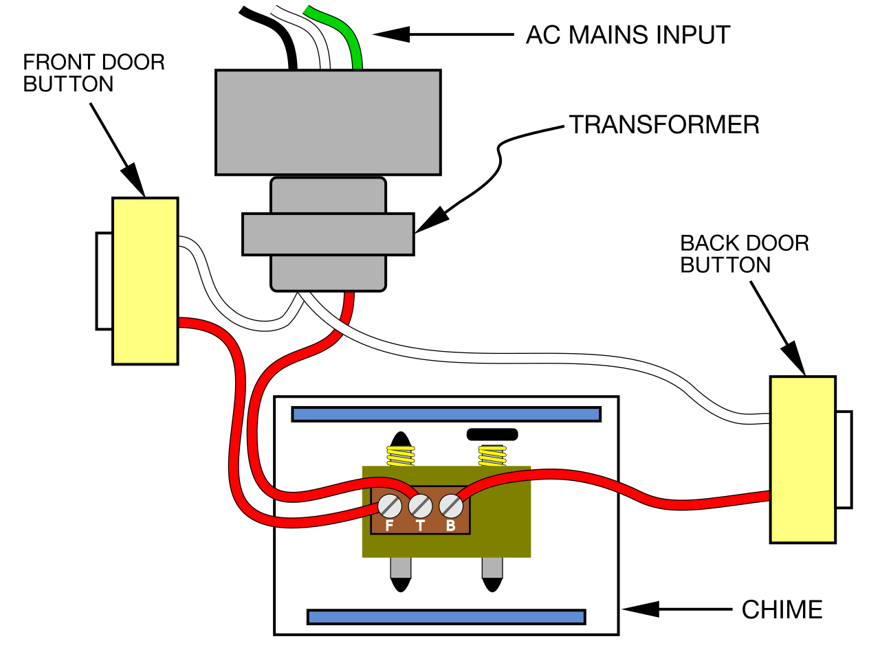
A “4 Wire Doorbell Wiring Diagram” illustrates the electrical connections for a four-wire doorbell system. In this configuration, a transformer, doorbell button, doorbell chime, and front and rear doorbell are connected using four wires: two for power and two for the chime. An example of such a system is in a multi-story home, where the doorbell chime is located on the first floor while the front doorbell is on the porch and the rear doorbell is by the back door.
4-wire doorbell wiring offers advantages like allowing multiple doorbells to be connected to the same chime, providing a stronger signal for long wire runs, and enabling the use of chimes with multiple melodies. Historically, the development of low-voltage transformers made it possible to power doorbells safely and efficiently.
This article delves into the details of 4-wire doorbell wiring diagrams, explaining the components, connections, and troubleshooting tips. It also discusses the advantages and limitations of this wiring method compared to other options.
When it comes to 4-wire doorbell wiring diagrams, understanding the essential aspects is crucial for proper installation and maintenance. These aspects encompass various dimensions, ranging from the components involved to the wiring connections and troubleshooting techniques.
- Components: Transformer, doorbell button, doorbell chime, front and rear doorbell
- Connections: Power wires, chime wires
- Wiring: Parallel or daisy chain
- Transformer: Voltage conversion, power supply
- Doorbell button: Triggers the chime
- Doorbell chime: Produces sound
- Front and rear doorbell: Notifies visitors
- Troubleshooting: Identifying and resolving issues
- Advantages: Multiple doorbells, long wire runs, multiple melodies
These aspects are interconnected and play vital roles in ensuring a functional doorbell system. For instance, the transformer provides the necessary power, while the doorbell button initiates the chime. Proper wiring ensures reliable connections, and troubleshooting techniques help diagnose and resolve issues. Understanding these aspects empowers individuals to install, maintain, and troubleshoot 4-wire doorbell systems effectively.
Components
Within the realm of 4-wire doorbell wiring diagrams, the components play a crucial role in ensuring the system’s functionality. These components, ranging from the transformer to the doorbell button, chime, and front and rear doorbells, work in tandem to facilitate communication between different parts of the system.
- Transformer: Responsible for converting household voltage to a lower voltage suitable for doorbell systems, typically 16-24 volts. This safety measure prevents electrical hazards and damage to components.
- Doorbell button: Initiates the doorbell system when pressed by a visitor. It completes the circuit, allowing current to flow and triggering the chime.
- Doorbell chime: Produces the audible signal when the doorbell button is pressed. It connects to the transformer and doorbell button via wires, enabling it to receive power and produce sound.
- Front and rear doorbell: Notifies occupants of visitors’ presence at the front or rear entrance of the building. These doorbells are connected to the chime and receive power from the transformer, allowing them to sound when the doorbell button is pressed.
These components collectively contribute to the effective operation of a 4-wire doorbell system. Proper selection, installation, and maintenance of these components are essential for ensuring reliable and efficient performance of the system.
Connections
Within the framework of “4 Wire Doorbell Wiring Diagram”, the aspect of “Connections: Power wires, chime wires” holds critical importance. These connections serve as the backbone of the system, allowing for the flow of electrical signals and power between various components.
-
Power wires:
Responsible for transmitting electrical power from the transformer to the doorbell button and chime. These wires typically carry a voltage of 16-24 volts, providing the necessary energy to operate the system. -
Chime wires:
Dedicated to carrying signals from the doorbell button to the chime. When the button is pressed, an electrical signal is sent through these wires, triggering the chime to produce sound. -
Parallel wiring:
A method of connecting multiple doorbells or chimes in parallel, allowing each device to operate independently. This configuration ensures that pressing any doorbell button will activate all connected chimes. -
Daisy chain wiring:
An alternative method of connecting multiple doorbells or chimes in series. In this setup, the output of one device is connected to the input of the next, forming a chain-like structure.
Understanding the proper connection of power wires and chime wires is crucial for a functional doorbell system. Incorrect wiring can lead to malfunctions, such as chimes not sounding or doorbells not working. By adhering to the correct wiring diagram and using appropriate wire gauges, installers can ensure a reliable and effective doorbell system.
Wiring
In the context of “4 Wire Doorbell Wiring Diagram”, the choice between parallel or daisy chain wiring is a crucial aspect that determines the system’s functionality and efficiency. The type of wiring directly affects the electrical connections and signal flow within the system.
Parallel wiring involves connecting multiple doorbells or chimes in parallel, meaning each device has its own dedicated power and signal wires. This configuration allows each doorbell or chime to operate independently, ensuring that pressing any button will activate the corresponding chime. Parallel wiring is commonly used when multiple doorbells or chimes are installed in different locations, such as on different floors of a building or at different entrances.
Daisy chain wiring, on the other hand, involves connecting multiple doorbells or chimes in series, where the output of one device is connected to the input of the next, forming a chain-like structure. This type of wiring is typically used when the devices are located close together, such as multiple doorbells on the same floor or in the same room. Daisy chain wiring requires fewer wires compared to parallel wiring, but it also introduces a dependency between the devices. If one device in the chain fails, it can affect the functionality of the subsequent devices.
Understanding the difference between parallel and daisy chain wiring and selecting the appropriate method is essential for a properly functioning 4-wire doorbell system. Parallel wiring offers greater flexibility and reliability, while daisy chain wiring is more cost-effective for certain applications. By considering the specific requirements and constraints of the installation, installers can determine the most suitable wiring method for their project.
Transformer
In the realm of 4-wire doorbell wiring diagrams, the transformer holds a position of critical importance, acting as the linchpin that enables the system to function effectively. Its primary role lies in voltage conversion, a process that adapts the standard household voltage to a level suitable for doorbell systems, typically ranging from 16 to 24 volts. This voltage reduction serves two crucial purposes: ensuring the safety of users and preventing damage to the delicate components within the doorbell system.
Without the voltage conversion performed by the transformer, the doorbell system would be exposed to the full force of household voltage, posing significant electrical hazards. The higher voltage could lead to electrical shocks, fires, or damage to the doorbell components. By reducing the voltage, the transformer safeguards both the individuals operating the system and the system itself, ensuring a safe and reliable operation.
Real-life examples of transformers in 4-wire doorbell wiring diagrams can be found in various residential and commercial settings. In a typical single-family home, a transformer is typically mounted near the electrical panel, where it converts the household voltage to the lower voltage required by the doorbell system. This transformer then supplies power to the doorbell button, chime, and front and rear doorbells, enabling them to operate as intended.
Understanding the connection between transformers and 4-wire doorbell wiring diagrams is essential for several practical reasons. Firstly, it allows for the safe and efficient installation and maintenance of doorbell systems. By comprehending the role of the transformer in voltage conversion, individuals can avoid electrical hazards and ensure the proper functioning of the system. Secondly, this understanding facilitates troubleshooting efforts. If a doorbell system malfunctions, knowing the transformer’s function and location enables homeowners to quickly identify and address potential issues.
Doorbell button
Within the framework of “4 Wire Doorbell Wiring Diagram”, the doorbell button serves as a crucial component, playing a central role in initiating the system’s primary function: alerting occupants to the presence of visitors. When a visitor presses the doorbell button, a circuit is completed, allowing electrical current to flow through the system. This triggers the doorbell chime, producing an audible signal that notifies occupants of the visitor’s arrival.
In essence, the doorbell button acts as a switch that controls the flow of electricity to the chime. Without this critical component, the system would be unable to perform its intended purpose of signaling the arrival of visitors. The button’s simplicity and reliability make it an indispensable part of any doorbell system, ensuring that occupants can be promptly notified of guests or deliveries.
Real-life examples of the doorbell button’s function within “4 Wire Doorbell Wiring Diagram” can be found in countless residential and commercial buildings. In a typical single-family home, the doorbell button is typically mounted near the front door, allowing visitors to easily announce their presence. When the button is pressed, it triggers the doorbell chime, which is often located inside the house, alerting the occupants to the visitor’s arrival.
Understanding the connection between “Doorbell button: Triggers the chime” and “4 Wire Doorbell Wiring Diagram” is essential for several practical reasons. Firstly, it enables individuals to troubleshoot and repair doorbell systems effectively. By comprehending the role of the doorbell button in completing the circuit and triggering the chime, homeowners can quickly identify and address issues such as a faulty button or loose connections.
Doorbell chime
Within the intricate network of a “4 Wire Doorbell Wiring Diagram”, the doorbell chime stands as a pivotal component, responsible for producing the audible signal that alerts occupants to the presence of visitors. Its function is deeply intertwined with the overall operation of the system, serving as the final link in the chain of events triggered by the doorbell button.
When a visitor presses the doorbell button, an electrical circuit is completed, allowing current to flow through the system. This current travels through the wires to the doorbell chime, where it triggers an electromagnet. The electromagnet then activates a hammer that strikes a set of chimes, producing the familiar sound that signals a visitor’s arrival. Without the doorbell chime, the system would be incomplete, lacking the essential auditory component that provides notification to occupants.
Real-life examples of “Doorbell chime: Produces sound” within “4 Wire Doorbell Wiring Diagram” can be observed in countless residential and commercial buildings. In a typical single-family home, the doorbell chime is typically mounted inside the house, often near the front door or in a central location. When the doorbell button is pressed, the chime produces a distinctive sound that can be easily heard throughout the house, alerting occupants to the visitor’s presence.
Understanding the connection between “Doorbell chime: Produces sound” and “4 Wire Doorbell Wiring Diagram” is essential for several practical reasons. Firstly, it enables individuals to troubleshoot and repair doorbell systems effectively. By comprehending the role of the doorbell chime in producing sound and its integration within the wiring diagram, homeowners can quickly identify and address issues such as a faulty chime or loose connections.
Front and rear doorbell
Within the intricate web of a “4 Wire Doorbell Wiring Diagram”, the front and rear doorbell serve as crucial components, fulfilling the essential function of notifying occupants of visitors at their doorstep. Their connection to the overall system and the cause-and-effect relationship they share with the wiring diagram are of paramount importance for a comprehensive understanding of doorbell systems.
When a visitor presses the doorbell button, an electrical circuit is completed, allowing current to flow through the wires and triggering a series of events. Within the 4-wire doorbell wiring diagram, the current travels from the button, through the transformer, and then to the front and rear doorbells. The current activates an electromagnet within each doorbell, which in turn causes a hammer to strike a set of chimes, producing the familiar sound that alerts occupants to the visitor’s presence. Without the front and rear doorbells, the system would be incomplete, lacking the essential auditory component that provides notification to occupants.
Real-life examples of “Front and rear doorbell: Notifies visitors” within “4 Wire Doorbell Wiring Diagram” can be observed in countless residential and commercial buildings. In a typical single-family home, the front doorbell is typically mounted near the front door, while the rear doorbell is located near the back door. When the doorbell button is pressed, both the front and rear doorbells produce a sound, ensuring that occupants can hear the notification regardless of their location within the house. In larger buildings, such as apartment complexes or office buildings, multiple front and rear doorbells may be installed to accommodate the needs of multiple tenants or occupants.
Understanding the connection between “Front and rear doorbell: Notifies visitors” and “4 Wire Doorbell Wiring Diagram” is essential for several practical reasons. Firstly, it enables individuals to troubleshoot and repair doorbell systems effectively. By comprehending the role of the front and rear doorbells in producing sound and their integration within the wiring diagram, homeowners or maintenance personnel can quickly identify and address issues such as a faulty doorbell or loose connections. Secondly, this understanding facilitates the design and installation of new doorbell systems. By considering the placement and wiring of the front and rear doorbells, installers can ensure optimal sound distribution and effective notification for occupants.
In conclusion, the connection between “Front and rear doorbell: Notifies visitors” and “4 Wire Doorbell Wiring Diagram” is a critical aspect of doorbell systems. The front and rear doorbells serve as the auditory endpoints of the system, providing occupants with a clear and reliable indication of visitors at their doorstep. Understanding this connection enables effective troubleshooting, design, and installation of doorbell systems, ensuring that occupants are always promptly notified of visitors.
Troubleshooting
Within the realm of “4 Wire Doorbell Wiring Diagram”, troubleshooting plays a pivotal role in ensuring the system’s optimal performance and longevity. Troubleshooting involves identifying and resolving issues that may arise during the installation, operation, or maintenance of the doorbell system. Its connection to the wiring diagram is inseparable, as the diagram provides a visual representation of the electrical connections and components within the system.
Consider a real-life scenario where a homeowner encounters a malfunctioning doorbell. The doorbell button may fail to trigger the chime, or the chime may produce a faint or distorted sound. By referring to the 4-wire doorbell wiring diagram, the homeowner can systematically troubleshoot the issue. The diagram helps identify the electrical connections associated with the doorbell button and chime, enabling the homeowner to check for loose connections, damaged wires, or faulty components.
Troubleshooting is a critical component of 4-wire doorbell wiring because it empowers individuals to address issues without relying solely on professional assistance. Armed with the wiring diagram and basic electrical knowledge, homeowners can perform simple repairs and maintenance tasks, saving time and expenses. Moreover, understanding troubleshooting techniques allows individuals to monitor the health of their doorbell system, identifying potential problems before they escalate into major issues.
In conclusion, the connection between “Troubleshooting: Identifying and resolving issues” and “4 Wire Doorbell Wiring Diagram” is essential for maintaining a functional and reliable doorbell system. The wiring diagram serves as a roadmap, guiding individuals through the electrical connections and components, while troubleshooting empowers them to diagnose and resolve issues effectively. This understanding fosters self-reliance, cost savings, and ensures the continued operation of the doorbell system.
Advantages
Within the framework of “4 Wire Doorbell Wiring Diagram”, the advantages of multiple doorbells, long wire runs, and multiple melodies hold significant importance, offering homeowners and installers a range of benefits and expanded functionality.
-
Multiple doorbells:
The ability to connect multiple doorbells to a single chime unit allows homeowners to install doorbells at different entrances or locations within their property. This ensures that visitors can easily alert occupants regardless of their entry point, enhancing convenience and security. -
Long wire runs:
4-wire doorbell wiring diagrams enable the use of longer wire runs compared to other wiring methods. This flexibility provides greater freedom in doorbell placement, allowing installers to reach distant locations or accommodate unique architectural designs without sacrificing signal strength or reliability. -
Multiple melodies:
Some doorbell chimes offer the option to choose from multiple melodies or sound effects. This customization allows homeowners to personalize their doorbell sound and differentiate between different entrances or visitors. Additionally, some chimes may feature adjustable volume levels for added convenience.
These advantages collectively contribute to the versatility and adaptability of 4-wire doorbell wiring diagrams. By allowing for multiple doorbells, long wire runs, and multiple melodies, homeowners can tailor their doorbell systems to meet their specific needs and preferences, enhancing both functionality and aesthetic appeal.


Related Posts


